Flat products made of steels for pressure purposes – Part 2: Non-alloy and alloy steels with specified elevated temperature properties
(Supersedes EN 10028-2:2009)
European foreword
This document (EN 10028-2:2017) has been prepared by Technical Committee ECISS/TC 107 "Steels for pressure purposes", the secretariat of which is held by DIN.
This European Standard shall be given the status of a national standard, either by publication of an identical text or by endorsement, at the latest by January 2018 and conflicting national standards shall be withdrawn at the latest by January 2018.
Attention is drawn to the possibility that some of the elements of this document may be the subject of patent rights. CEN [and/or CENELEC] shall not be held responsible for identifying any or all such patent rights.
This document supersedes EN 10028-2:2009.
This document has been prepared under a mandate given to CEN by the European Commission and the European Free Trade Association, and supports essential requirements of Directive 2014/68/EU.
For relationship with Directive 2014/68/EU, see informative Annex ZA, which is an integral part of this document.
A list of changes between this document and the previous version can be found in Annex F.
According to the CEN-CENELEC Internal Regulations, the national standards organizations of the following countries are bound to implement this European Standard: Austria, Belgium, Bulgaria, Croatia, Cyprus, Czech Republic, Denmark, Estonia, Finland, Former Yugoslav Republic of Macedonia, France, Germany, Greece, Hungary, Iceland, Ireland, Italy, Latvia, Lithuania, Luxembourg, Malta, Netherlands, Norway, Poland, Portugal, Romania, Serbia, Slovakia, Slovenia, Spain, Sweden, Switzerland, Turkey and the United Kingdom.
1 Scope
This European Standard specifies requirements for flat products for pressure equipment made of weldable non-alloy and alloy steels with elevated temperature properties as specified in Table 1. The requirements and definitions of EN 10028-1:2017 also apply.
NOTE Once this European Standard is published in the EU Official Journal (OJEU) under Directive 2014/68/EU, presumption of conformity to the Essential Safety Requirements (ESRs) of Directive 2014/68/EU is limited to technical data of materials in this European Standard (Part 1 and this Part 2 of the series) and does not presume adequacy of the material to a specific item of equipment. Consequently, the assessment of the technical data stated in this material standard against the design requirements of this specific item of equipment to verify that the ESRs of Directive 2014/68/EU are satisfied, needs to be done.
2 Normative references
The following documents, in whole or in part, are normatively referenced in this document and are indispensable for its application. For dated references, only the edition cited applies. For undated references, the latest edition of the referenced document (including any amendments) applies.
- EN 1011-1:2009, Welding - Recommendations for welding of metallic materials - Part 1: General guidance for arc welding
- EN 1011-2:2001, Welding - Recommendations for welding of metallic materials - Part 2: Arc welding of ferritic steels
- EN 10028-1:2017, Flat products made of steels for pressure purposes - Part 1: General requirements
- EN 10204:2004, Metallic products - Types of inspection documents
- EN 10229:1998, Evaluation of resistance of steel products to hydrogen induced cracking (HIC)
3 Terms and definitions
For the purposes of this document, the terms and definitions given in EN 10028-1:2017 apply.
4 Tolerances on dimensions
See EN 10028-1:2017.
5 Calculation of mass
See EN 10028-1:2017.
6 Classification and designation
In accordance with EN 10020, the grades P235GH, P265GH, P295GH and P355GH are non-alloy quality steels. All other grades are alloy special steels.
See EN 10028-1:2017.
7 Information to be supplied by the purchaser
See EN 10028-1:2017.
A number of options are specified in this document and listed below. Additionally the relevant options of EN 10028-1:2017 apply. If the purchaser does not indicate a wish to implement any of these options at the time of enquiry and order, the products shall be supplied in accordance with the basic specification (see also EN 10028-1:2017).
- 1) limitation of copper and/or tin content (see Table 1, footnote b);
- 2) minimum chromium content of 0.80% (see Table 1, footnote f);
- 3) maximum carbon content of 0.17% for nominal thicknesses greater than 150 mm (see Table 1, footnote g);
- 4) tests in the simulated normalized condition (see 8.2.2);
- 5) delivery conditions deviating from those specified in Table 3 (see 8.2.2 and 8.2.3);
- 6) maximum carbon equivalent value for P235GH, P265GH, P295GH and P355GH (see 8.3.3);
- 7) specification of a minimum impact energy of 40 J (see Table 3);
- 8) no option, intentionally left blank;
- 9) specification of the delivery condition +QT where the usual delivery condition is +NT (see Table 3, footnote b and Table 4, footnote b);
- 10) additional impact energy values (see Table 3, footnote e);
- 11) no option, intentionally left blank;
- 12) HIC test in accordance with EN 10229 (see 8.7);
- 13) step cooling test in accordance with Annex E (see 8.8);
- 14) mid thickness test pieces for the impact test (see Clause 10).
10 plates with nominal dimensions, thickness = 50 mm, width = 2000 mm, length = 10000 mm, made of a steel grade with the name 16Mo3 and the number 1.5415 as specified in EN 10028-2, inspection certificate 3.1 as specified in EN 10204:
10 plates – 50 x 2 000 x 10 000 – EN 10028-2 – 16Mo3 – Inspection certificate 3.1 or 10 plates – 50 x 2 000 x 10 000 – EN 10028-2 – 1.5415 – Inspection certificate 3.1
8 Requirements
See EN 10028-1:2017.
8.2 Delivery condition
8.2.1 Unless otherwise agreed at the time of enquiry and order, the products covered by this document shall be supplied in the usual conditions given in Table 3 (see 8.2.3).
8.2.2 Normalizing may, at the discretion of manufacturer, be replaced with normalizing rolling for the steel grades P235GH, P265GH, P295GH, P355GH and 16Mo3. In this case, additional tests in the simulated normalized condition with an agreed frequency of testing may be agreed at the time of enquiry and order to verify that the specified properties are complied with.
8.2.3 If so agreed at the time of enquiry and order, products made of steel grades P235GH, P265GH, P295GH, P355GH and 16Mo3 may also be delivered in the untreated condition. Products made of one of the other alloy grades may be supplied in the tempered or normalized condition or, in exceptional cases, in the untreated condition if so agreed (Annex A contains heat treatment information for the purchaser). In these cases, testing shall be carried out on test pieces in the usual delivery condition as indicated in Table 3.
8.2.4 Information on welding are given in Annex B of this standard.
8.3 Chemical composition
8.3.1 The requirements of Table 1 shall apply for the chemical composition according to the cast analysis.
8.3.2 The product analysis shall not deviate from the specified values for the cast analysis as specified in Table 1 by more than the values given in Table 2.
8.3.3 A maximum value for the carbon equivalent may be agreed at time of enquiry and order for steel grades P235GH, P265GH, P295GH and P355GH. In this case, the following formula shall apply for calculation of the carbon equivalent value (CEV):
CEV = C + Mn/6 + (Cr + Mo + V)/5 + (Ni + Cu)/15
| Steel designation | % by mass | |||||||||||||||
|---|---|---|---|---|---|---|---|---|---|---|---|---|---|---|---|---|
| Steel name | Steel number | C | Si | Mn | P max. |
S max. |
Altotal | N | Cr | Cu b | Mo | Nb | Ni | Ti max. |
V | Others |
| P235GH | 1.0345 | ≤ 0,16 | ≤ 0,35 | 0,60 c to 1,20 | 0,025 | 0,010 | ≥ 0,020 | ≤ 0,012 d | ≤ 0,30 | ≤ 0,30 | ≤ 0,08 | ≤ 0,030 | ≤ 0,30 | 0,03 | ≤ 0,02 | Cr+Cu+Mo+Ni ≤ 0,70 |
| P265GH | 1.0425 | ≤ 0,20 | ≤ 0,40 | 0,80 c to 1,40 | 0,025 | 0,010 | ≥ 0,020 | ≤ 0,012 d | ≤ 0,30 | ≤ 0,30 | ≤ 0,08 | ≤ 0,030 | ≤ 0,30 | 0,03 | ≤ 0,02 | |
| P295GH | 1.0481 | 0,08 to 0,20 | ≤ 0,40 | 0,90 c to 1,50 | 0,025 | 0,010 | ≥ 0,020 | ≤ 0,012 d | ≤ 0,30 | ≤ 0,30 | ≤ 0,08 | ≤ 0,030 | ≤ 0,30 | 0,03 | ≤ 0,02 | |
| P355GH | 1.0473 | 0,10 to 0,22 | ≤ 0,60 | 1,10 to 1,70 | 0,025 | 0,010 | ≥ 0,020 | ≤ 0,012 d | ≤ 0,30 | ≤ 0,30 | ≤ 0,08 | ≤ 0,040 | ≤ 0,30 | 0,03 | ≤ 0,02 | |
| 16Mo3 | 1.5415 | 0,12 to 0,20 | ≤ 0,35 | 0,40 to 0,90 | 0,025 | 0,010 | e | ≤ 0,012 | ≤ 0,30 | ≤ 0,30 | 0,25 to 0,35 | - | ≤ 0,30 | - | - | - |
| 18MnMo4-5 | 1.5414 | ≤ 0,20 | ≤ 0,40 | 0,90 to 1,50 | 0,015 | 0,005 | e | ≤ 0,012 | ≤ 0,30 | ≤ 0,30 | 0,45 to 0,60 | - | ≤ 0,30 | - | - | - |
| 20MnMoNi4-5 | 1.6311 | 0,15 to 0,23 | ≤ 0,40 | 1,00 to 1,50 | 0,020 | 0,010 | e | ≤ 0,012 | ≤ 0,20 | ≤ 0,20 | 0,45 to 0,60 | - | 0,40 to 0,80 | - | ≤ 0,02 | - |
| 15NiCuMoNb5-6-4 | 1.6368 | ≤ 0,17 | 0,25 to 0,50 | 0,80 to 1,20 | 0,025 | 0,010 | ≥ 0,015 | ≤ 0,020 | ≤ 0,30 | 0,50 to 0,80 | 0,25 to 0,50 | 0,015 to 0,045 | 1,00 to 1,30 | - | - | - |
| 13CrMo4-5 | 1.7335 | 0,08 to 0,18 | ≤ 0,35 | 0,40 to 1,00 | 0,025 | 0,010 | e | ≤ 0,012 | 0,70 f to 1,15 | ≤ 0,30 | 0,40 to 0,60 | - | - | - | - | - |
| 13CrMoSi5-5 | 1.7336 | ≤ 0,17 | 0,50 to 0,80 | 0,40 to 0,60 | 0,015 | 0,005 | e | ≤ 0,012 | 1,00 to 1,50 | ≤ 0,30 | 0,45 to 0,65 | - | ≤ 0,30 | - | - | - |
| 10CrMo9-10 | 1.7380 | 0,08 to 0,14 g | ≤ 0,50 | 0,40 to 0,80 | 0,020 | 0,010 | e | ≤ 0,012 | 2,00 to 2,50 | ≤ 0,30 | 0,90 to 1,10 | - | - | - | - | - |
| 12CrMo9-10 | 1.7375 | 0,10 to 0,15 | ≤ 0,30 | 0,30 to 0,80 | 0,015 | 0,010 | e | ≤ 0,012 | 2,00 to 2,50 | ≤ 0,25 | 0,90 to 1,10 | - | ≤ 0,30 | - | - | - |
| X12CrMo5 | 1.7362 | 0,10 to 0,15 | ≤ 0,50 | 0,30 to 0,60 | 0,020 | 0,005 | e | ≤ 0,012 | 4,00 to 6,00 | ≤ 0,30 | 0,45 to 0,65 | - | ≤ 0,30 | - | - | - |
| 13CrMoV9-10 | 1.7703 | 0,11 to 0,15 | ≤ 0,10 | 0,30 to 0,60 | 0,015 | 0,005 | e | ≤ 0,012 | 2,00 to 2,50 | ≤ 0,20 | 0,90 to 1,10 | ≤ 0,07 | ≤ 0,25 | 0,03 | 0,25 to 0,35 | B ≤ 0,002, Ca ≤ 0,015 |
| 12CrMoV12-10 | 1.7767 | 0,10 to 0,15 | ≤ 0,15 | 0,30 to 0,60 | 0,015 | 0,005 | e | ≤ 0,012 | 2,75 to 3,25 | ≤ 0,25 | 0,90 to 1,10 | ≤ 0,07 h | ≤ 0,25 | 0,03h | 0,20 to 0,30 | B ≤ 0,003 h, Ca ≤ 0,015 h |
| X10CrMoVNb9-1 | 1.4903 | 0,08 to 0,12 | ≤ 0,50 | 0,30 to 0,60 | 0,020 | 0,005 | ≤ 0,040 | 0,030 to 0,070 | 8,00 to 9,50 | ≤ 0,30 | 0,85 to 1,05 | 0,06 to 0,10 | ≤ 0,30 | - | 0,18 to 0,25 | - |
|
a Elements not listed in this table shall not be intentionally added to the steel without the agreement of the purchaser except for finishing the cast. All appropriate measures shall be taken to prevent the addition from scrap or other materials used in steelmaking of these elements which may affect the mechanical properties and usability. b A lower maximum copper content and/or a maximum sum of copper and tin content, e.g. Cu + 6 Sn ≤ 0,33 %, may be agreed upon at the time of enquiry and order, e.g. with regard to hot formability for the grades where only a maximum copper content is specified. c For nominal thicknesses < 6 mm, a minimum manganese content of 0,20 % lower than specified is permitted. d A ratio Al\N ≥2 shall apply. e The Al content of the cast shall be determined and given in the inspection document. f If resistance to pressurized hydrogen is of importance, a minimum content of 0,80 % Cr may be agreed upon at the time of enquiry and order. g For nominal thicknesses greater than 150 mm, a maximum content of 0,17 % C may be agreed upon at the time of enquiry and order. h This grade may be produced with additions of either Ti + B or Nb + Ca. The following minimum contents shall apply: Ti ≥ 0,015 % and B ≥ 0,001 % in the case of additions of Ti + B, Nb ≥ 0,015 % and Ca ≥ 0,000 5 % in the case of additions of Nb + Ca. |
||||||||||||||||
| Element | Specified value in the cast analysis according to Table 1 % by mass |
Permissible deviation a of the product analysis % by mass |
|---|---|---|
| C | ≤ 0,23 | ±0,02 |
| Si | ≤ 0,35 | ±0,05 |
| 0,35 to ≤ 1,00 | ±0,06 | |
| Mn | ≤ 1,00 | ±0,05 |
| 1,00 to ≤ 1,70 | ±0,10 | |
| P | ≤ 0,015 | + 0,003 |
| 0,015 to ≤ 0,025 | + 0,005 | |
| S | ≤ 0,010 | + 0,003 |
| Al | ≥ 0,010 | ±0,005 |
| B | ≤ 0,003 | ±0,000 5 |
| N | ≤ 0,020 | ±0,002 |
| 0,020 to ≤ 0,070 | ±0,005 | |
| Cr | ≤ 2,00 | ±0,05 |
| 2,00 to ≤ 10,00 | ±0,10 | |
| 10,00 | ±0,10 | |
| Cu | ≤ 0,30 | ±0,05 |
| 0,30 to ≤ 0,80 | ±0,10 | |
| Mo | ≤ 0,35 | ±0,03 |
| 0,35 to ≤ 1,10 | ±0,04 | |
| Nb | ≤ 0,10 | ±0,01 |
| Ni | ≤ 0,30 | ±0,05 |
| 0,30 to ≤ 1,30 | ±0,10 | |
| Cr+Cu+Mo+Ni | ≤ 0,70 | + 0,05 |
| Ti | ≤ 0,03 | ±0,01 |
| V | ≤ 0,05 | ±0,01 |
| 0,05 to ≤ 0,35 | ±0,03 | |
| a If several product analyses are carried out on one cast, and the contents of an individual element determined lie outside the permissible range of the chemical composition specified for the cast analysis then it is only allowed to exceed the permissible maximum value or fall short of the permissible minimum value, but not both for one cast. | ||
8.4 Mechanical properties
8.4.1 The values given in Tables 3 and 4 (see also EN 10028-1:2017 and Clause 10) shall apply.
8.4.2 Annex C gives mean values as preliminary data for the purchaser about 1% (plastic) creep strain and creep rupture.
| Steel grade | Usual delivery condition a b | Nominal thickness t mm |
Tensile properties at room temperature | Impact energy KV2 J min. at a temperature in °C of |
|||||
|---|---|---|---|---|---|---|---|---|---|
| Steel name | Steel number | Yield strength ReH MPa min |
Tensile strength Rm MPa |
Elongation after fracture A % min. |
-20 f | 0 f | +20 | ||
| P235GH | 1.0345 | +N c | ≤ 16 | 235 | 360 to 480 | 24 | 27 | 34 | 40 |
| 16 < t ≤ 40 | 225 | ||||||||
| 40 < t ≤ 60 | 215 | ||||||||
| 60 < t ≤ 100 | 200 | ||||||||
| 100 < t ≤ 150 | 185 | 350 to 480 | |||||||
| 150 < t ≤ 250 | 170 | 340 to 480 | |||||||
| P265GH | 1.0425 | +N c | ≤ 16 | 265 | 410 to 530 | 22 | 27 | 34 | 40 |
| 16 < t ≤ 40 | 255 | ||||||||
| 40 < t ≤ 60 | 245 | ||||||||
| 60 < t ≤ 100 | 215 | ||||||||
| 100 < t ≤ 150 | 200 | 400 to 530 | |||||||
| 150 < t ≤ 250 | 185 | 390 to 530 | |||||||
| P295GH | 1.0481 | +N c | ≤ 16 | 295 | 460 to 580 | 21 | 27 | 34 | 40 |
| 16 < t ≤ 40 | 290 | ||||||||
| 40 < t ≤ 60 | 285 | ||||||||
| 60 < t ≤ 100 | 260 | ||||||||
| 100 < t ≤ 150 | 235 | 440 to 570 | |||||||
| 150 < t ≤ 250 | 220 | 430 to 570 | |||||||
| P355GH | 1.0473 | +N c | ≤ 16 | 355 | 510 to 650 | 20 | 27 | 34 | 40 |
| 16 < t ≤ 40 | 345 | ||||||||
| 40 < t ≤ 60 | 335 | ||||||||
| 60 < t ≤ 100 | 315 | 490 to 630 | |||||||
| 100 < t ≤ 150 | 295 | 480 to 630 | |||||||
| 150 < t ≤ 250 | 280 | 470 to 630 | |||||||
| 16Mo3 | 1.5415 | +N c d | ≤ 16 | 275 | 440 to 590 | 22 | e | e | 31 f |
| 16 < t ≤ 40 | 270 | ||||||||
| 40 < t ≤ 60 | 260 | ||||||||
| 60 < t ≤ 100 | 240 | 430 to 580 | |||||||
| 100 < t ≤ 150 | 220 | 420 to 570 | |||||||
| 150 < t ≤ 250 | 210 | 410 to 570 | |||||||
| 18MnMo4-5 | 1.5414 | +NT | ≤ 60 | 345 | 510 to 650 | 20 | 27 | 34 | 40 |
| 60 < t ≤ 150 | 325 | ||||||||
| +QT | 150 < t ≤ 250 | 310 | 480 to 620 | ||||||
| 20MnMoNi4-5 | 1.6311 | +QT | ≤ 40 | 470 | 590 to 750 | 18 | 27 | 40 | 50 |
| 40 < t ≤ 60 | 460 | 590 to 730 | |||||||
| 60 < t ≤ 100 | 450 | 570 to 710 | |||||||
| 100 < t ≤ 150 | 440 | 570 to 710 | |||||||
| 150 < t ≤ 250 | 400 | 560 to 700 | |||||||
| 15NiCuMoNb5-6-4 | 1.6368 | +NT | ≤ 40 | 460 | 610 to 780 | 16 | 27 | 34 | 40 |
| 40 < t ≤ 60 | 440 | 610 to 780 | |||||||
| 60 < t ≤ 100 | 430 | 600 to 760 | |||||||
| +NT or +QT | 100 < t ≤ 150 | 420 | 590 to 740 | ||||||
| +QT | 150 < t ≤ 200 | 410 | 580 to 740 | ||||||
| 13CrMo4-5 | 1.7335 | +NT | ≤ 16 | 300 | 450 to 600 | 19 | e | e | 31 f |
| 16 < t ≤ 60 | 290 | 450 to 600 | 31 f | ||||||
| 60 < t ≤ 100 | 270 | 440 to 590 | 27 f | ||||||
| +NT or +QT | 100 < t ≤ 150 | 255 | 430 to 580 | e | e | 27 f | |||
| +QT | 150 < t ≤ 250 | 245 | 420 to 570 | e | e | 27 f | |||
| 13CrMoSi5-5 | 1.7336 | +NT | ≤ 60 | 310 | 510 to 690 | 20 | e | 27 | 34 f |
| 60 < t ≤ 100 | 300 | 480 to 660 | |||||||
| +QT | ≤ 60 | 400 | 510 to 690 | 27 | 34 | 40 | |||
| 60 < t ≤ 100 | 390 | 500 to 680 | |||||||
| 100 < t ≤ 250 | 380 | 490 to 670 | |||||||
| 10CrMo9-10 | 1.7380 | +NT | ≤ 16 | 310 | 480 to 630 | 18 | e | e | 31 f |
| 16 < t ≤ 40 | 300 | ||||||||
| 40 < t ≤ 60 | 290 | ||||||||
| +NT or +QT | 60 < t ≤ 100 | 280 | 470 to 620 | 17 | 27 f | ||||
| 100 < t ≤ 150 | 260 | 460 to 610 | |||||||
| +QT | 150 < t ≤ 250 | 250 | 450 to 600 | ||||||
| 12CrMo9-10 | 1.7375 | + NT or +QT | ≤ 250 | 355 | 540 to 690 | 18 | 27 | 40 | 70 |
| X12CrMo5 | 1.7362 | +NT | ≤ 60 | 320 | 510 to 690 | 20 | 27 | 34 | 40 |
| 60 < t ≤ 150 | 300 | 480 to 660 | |||||||
| +QT | 150 < t ≤ 250 | 300 | 450 to 630 | ||||||
| 13CrMoV9-10 | 1.7703 | + NT | ≤ 60 | 455 | 600 to 780 | 18 | 27 | 34 | 40 |
| 60 < t ≤ 150 | 435 | 590 to 770 | |||||||
| + QT | 150 < t ≤ 250 | 415 | 580 to 760 | ||||||
| 12CrMoV12-10 | 1.7767 | +NT | ≤ 60 | 455 | 600 to 780 | 18 | 27 | 34 | 40 |
| 60 < t ≤ 150 | 435 | 590 to 770 | |||||||
| +QT | 150 < t ≤ 250 | 415 | 580 to 760 | ||||||
| X10CrMoVNb9-1 | 1.4903 | +NT | ≤ 60 | 445 | 580 to 760 | 18 | 27 | 34 | 40 |
| 60 < t ≤ 150 | 435 | 550 to 730 | |||||||
| +QT | 150 < t ≤ 250 | 435 | 520 to 700 | ||||||
|
a +N = normalized; +NT = normalized and tempered; +QT = quenched and tempered. b For product thicknesses, where the usual delivery condition is +NT, the delivery condition +QT may be agreed. c See 8.2.2. d This steel may also be supplied in the +NT condition at the discretion of the manufacturer. e A value may be agreed at the time of enquiry and order. f An impact energy value of 40 J may be agreed at the time of enquiry and order. |
|||||||||
| Steel grade | Nominal thickness b t mm |
Minimum 0,2 % proof strength Rp0,2 MPa at a temperature in °C of |
||||||||||
|---|---|---|---|---|---|---|---|---|---|---|---|---|
| Steel name | Steel number | 50 | 100 | 150 | 200 | 250 | 300 | 350 | 400 | 450 | 500 | |
| P235GH | 1.0345 | ≤ 16 | 227 | 214 | 198 | 182 | 167 | 153 | 142 | 133 | - | - |
| 16 < t ≤ 40 | 218 | 205 | 190 | 174 | 160 | 147 | 136 | 128 | - | - | ||
| 40 < t ≤ 60 | 208 | 196 | 181 | 167 | 153 | 140 | 130 | 122 | - | - | ||
| 60 < t ≤ 100 | 193 | 182 | 169 | 155 | 142 | 130 | 121 | 114 | - | - | ||
| 100 < t ≤ 150 | 179 | 168 | 156 | 143 | 131 | 121 | 112 | 105 | - | - | ||
| 150 < t ≤ 250 | 164 | 155 | 143 | 132 | 121 | 111 | 103 | 97 | - | - | ||
| P265GH | 1.0425 | ≤ 16 | 256 | 241 | 223 | 205 | 188 | 173 | 160 | 150 | - | - |
| 16 < t ≤ 40 | 247 | 232 | 215 | 197 | 181 | 166 | 154 | 145 | - | - | ||
| 40 < t ≤ 60 | 237 | 223 | 206 | 190 | 174 | 160 | 148 | 139 | - | - | ||
| 60 < t ≤ 100 | 208 | 196 | 181 | 167 | 153 | 140 | 130 | 122 | - | - | ||
| 100 < t ≤ 150 | 193 | 182 | 169 | 155 | 142 | 130 | 121 | 114 | - | - | ||
| 150 < t ≤ 250 | 179 | 168 | 156 | 143 | 131 | 121 | 112 | 105 | - | - | ||
| P295GH | 1.0481 | ≤ 16 | 285 | 268 | 249 | 228 | 209 | 192 | 178 | 167 | - | - |
| 16 < t ≤ 40 | 280 | 264 | 244 | 225 | 206 | 189 | 175 | 165 | - | - | ||
| 40 < t ≤ 60 | 276 | 259 | 240 | 221 | 202 | 186 | 172 | 162 | - | - | ||
| 60 < t ≤ 100 | 251 | 237 | 219 | 201 | 184 | 170 | 157 | 148 | - | - | ||
| 100 < t ≤ 150 | 227 | 214 | 198 | 182 | 167 | 153 | 142 | 133 | - | - | ||
| 150 < t ≤ 250 | 213 | 200 | 185 | 170 | 156 | 144 | 133 | 125 | - | - | ||
| P355GH | 1.0473 | ≤ 16 | 343 | 323 | 299 | 275 | 252 | 232 | 214 | 202 | - | - |
| 16 < t ≤ 40 | 334 | 314 | 291 | 267 | 245 | 225 | 208 | 196 | - | - | ||
| 40 < t ≤ 60 | 324 | 305 | 282 | 259 | 238 | 219 | 202 | 190 | - | - | ||
| 60 < t ≤ 100 | 305 | 287 | 265 | 244 | 224 | 206 | 190 | 179 | - | - | ||
| 100 < t ≤ 150 | 285 | 268 | 249 | 228 | 209 | 192 | 178 | 167 | - | - | ||
| 150 < t ≤ 250 | 271 | 255 | 236 | 217 | 199 | 183 | 169 | 159 | - | - | ||
| 16Mo3 | 1.5415 | ≤ 16 | 273 | 264 | 250 | 233 | 213 | 194 | 175 | 159 | 147 | 141 |
| 16 < t ≤ 40 | 268 | 259 | 245 | 228 | 209 | 190 | 172 | 156 | 145 | 139 | ||
| 40 < t ≤ 60 | 258 | 250 | 236 | 220 | 202 | 183 | 165 | 150 | 139 | 134 | ||
| 60 < t ≤ 100 | 238 | 230 | 218 | 203 | 186 | 169 | 153 | 139 | 129 | 123 | ||
| 100 < t ≤ 150 | 218 | 211 | 200 | 186 | 171 | 155 | 140 | 127 | 118 | 113 | ||
| 150 < t ≤ 250 | 208 | 202 | 191 | 178 | 163 | 148 | 134 | 121 | 113 | 108 | ||
| 18MnMo4-5 c | 1.5414 | ≤ 60 | 330 | 320 | 315 | 310 | 295 | 285 | 265 | 235 | 215 | - |
| 60 < t ≤ 150 | 320 | 310 | 305 | 300 | 285 | 275 | 255 | 225 | 205 | - | ||
| 150 < t ≤ 250 | 310 | 300 | 295 | 290 | 275 | 265 | 245 | 220 | 200 | - | ||
| 20MnMoNi4-5 | 1.6311 | ≤ 40 | 460 | 448 | 439 | 432 | 424 | 415 | 402 | 384 | - | - |
| 40 < t ≤ 60 | 450 | 438 | 430 | 423 | 415 | 406 | 394 | 375 | - | - | ||
| 60 < t ≤ 100 | 441 | 429 | 420 | 413 | 406 | 398 | 385 | 367 | - | - | ||
| 100 < t ≤ 150 | 431 | 419 | 411 | 404 | 397 | 389 | 377 | 359 | - | - | ||
| 150 < t ≤ 250 | 392 | 381 | 374 | 367 | 361 | 353 | 342 | 327 | - | - | ||
| 15NiCuMoNb5-6-4 | 1.6368 | ≤ 40 | 447 | 429 | 415 | 403 | 391 | 380 | 366 | 351 | 331 | - |
| 40 < t ≤ 60 | 427 | 410 | 397 | 385 | 374 | 363 | 350 | 335 | 317 | - | ||
| 60 < t ≤ 100 | 418 | 401 | 388 | 377 | 366 | 355 | 342 | 328 | 309 | - | ||
| 100 < t ≤ 150 | 408 | 392 | 379 | 368 | 357 | 347 | 335 | 320 | 302 | - | ||
| 150 < t ≤ 200 | 398 | 382 | 370 | 359 | 349 | 338 | 327 | 313 | 295 | - | ||
| 13CrMo4-5 | 1.7335 | ≤ 16 | 294 | 285 | 269 | 252 | 234 | 216 | 200 | 186 | 175 | 164 |
| 16 < t ≤ 60 | 285 | 275 | 260 | 243 | 226 | 209 | 194 | 180 | 169 | 159 | ||
| 60 < t ≤ 100 | 265 | 256 | 242 | 227 | 210 | 195 | 180 | 168 | 157 | 148 | ||
| 100 < t ≤ 150 | 250 | 242 | 229 | 214 | 199 | 184 | 170 | 159 | 148 | 139 | ||
| 150 < t ≤ 250 | 235 | 223 | 215 | 211 | 199 | 184 | 170 | 159 | 148 | 139 | ||
| 13CrMoSi5-5+NT | 1.7336+NT | ≤ 60 | 299 | 283 | 268 | 255 | 244 | 233 | 223 | 218 | 206 | - |
| 60 < t ≤ 100 | 289 | 274 | 260 | 247 | 236 | 225 | 216 | 211 | 199 | - | ||
| 13CrMoSi5-5+QT | 1.7336+QT | ≤ 60 | 384 | 364 | 352 | 344 | 339 | 335 | 330 | 322 | 309 | - |
| 60 < t ≤ 100 | 375 | 355 | 343 | 335 | 330 | 327 | 322 | 314 | 301 | - | ||
| 100 < t ≤ 250 | 365 | 346 | 334 | 326 | 322 | 318 | 314 | 306 | 293 | - | ||
| 10CrMo9-10 | 1.7380 | ≤ 16 | 288 | 266 | 254 | 248 | 243 | 236 | 225 | 212 | 197 | 185 |
| 16 < t ≤ 40 | 279 | 257 | 246 | 240 | 235 | 228 | 218 | 205 | 191 | 179 | ||
| 40 < t ≤ 60 | 270 | 249 | 238 | 232 | 227 | 221 | 211 | 198 | 185 | 173 | ||
| 60 < t ≤ 100 | 260 | 240 | 230 | 224 | 220 | 213 | 204 | 191 | 178 | 167 | ||
| 100 < t ≤ 150 | 250 | 237 | 228 | 222 | 219 | 213 | 204 | 191 | 178 | 167 | ||
| 150 < t ≤ 250 | 240 | 227 | 219 | 213 | 210 | 208 | 204 | 191 | 178 | 167 | ||
| 12CrMo9-10 | 1.7375 | ≤ 250 | 341 | 323 | 311 | 303 | 298 | 295 | 292 | 287 | 279 | - |
| X12CrMo5 | 1.7362 | ≤ 60 | 310 | 299 | 295 | 294 | 293 | 291 | 285 | 273 | 253 | 222 |
| 60 < t ≤ 250 | 290 | 281 | 277 | 275 | 275 | 273 | 267 | 256 | 237 | 208 | ||
| 13CrMoV9-10 c | 1.7703 | ≤ 60 | 410 | 395 | 380 | 375 | 370 | 365 | 362 | 360 | 350 | - |
| 60 < t ≤ 250 | 405 | 390 | 370 | 365 | 360 | 355 | 352 | 350 | 340 | - | ||
| 12CrMoV12-10 c | 1.7767 | ≤ 60 | 410 | 395 | 380 | 375 | 370 | 365 | 362 | 360 | 350 | - |
| 60 < t ≤ 250 | 405 | 390 | 370 | 365 | 360 | 355 | 352 | 350 | 340 | - | ||
| X10CrMoVNb9-1 | 1.4903 | ≤ 60 | 432 | 415 | 401 | 392 | 385 | 379 | 373 | 364 | 349 | 324 |
| 60 < t ≤ 250 | 423 | 406 | 392 | 383 | 376 | 371 | 365 | 356 | 341 | 316 | ||
|
a The values correspond to the lower band of the relevant trend curve determined in accordance with EN 10314 with a confidence limit of about 98 % (2 s). b Delivery condition as given in Table 3 (but see footnote b to Table 3). c Rp0,2 not determined in accordance with EN 10314. They are minimum values of the scatter band considered until now. |
||||||||||||
8.5 Surface condition
See EN 10028-1:2017.
8.6 Internal soundness
See EN 10028-1:2017.
8.7 Resistance to hydrogen induced cracking
Carbon and low alloy steels may be susceptible to cracking when exposed to corrosive H2S containing environments, usually referred to as 'sour service'. A test to evaluate the resistance to hydrogen induced cracking in accordance with Annex D may be specified at time of enquiry and order.
8.8 Embrittlement of CrMo steels
CrMo steels may tend to become brittle in service at temperatures between approximately 400°C and 500°C. This possible tendency for embrittlement can be simulated in the laboratory with the so called step cooling test. In this test a specimen is exposed to a temperature - time cycle as given in Figure E.1. The shift of a transition curve before and after the step cooling test is a measure for the embrittlement. A step cooling test in accordance with Annex E may be specified at time of enquiry and order.
9 Inspection
See EN 10028-1:2017 and 8.7 and 8.8.
10 Sampling
See EN 10028-1:2017.
For the impact test, deviating from EN 10028-1:2017, Table 4, footnote g, the preparation of test pieces taken from the mid thickness may be agreed at the time of enquiry and order. In this case, test temperatures and minimum impact energy values shall also be agreed.
11 Test methods
See EN 10028-1:2017 and Annex D and E.
12 Marking
See EN 10028-1:2017.
Annex A (informative) Guidelines for heat treatment
| Steel grade | Temperature, °C | |||
|---|---|---|---|---|
| Steel name | Steel number | Normalizing | Quenching | Tempering b |
| P235GH | 1.0345 | 890 to 950 a | - | - |
| P265GH | 1.0425 | 890 to 950 a | - | - |
| P295GH | 1.0481 | 890 to 950 a | - | - |
| P355GH | 1.0473 | 890 to 950 a | - | - |
| 16Mo3 | 1.5415 | 890 to 950 a | - | c |
| 18MnMo4-5 | 1.5414 | 890 to 950 | 600 to 640 | |
| 20MnMoNi4-5 | 1.6311 | - | 870 to 940 | 610 to 690 |
| 15NiCuMoNb5-6-4 | 1.6368 | 880 to 960 | 580 to 680 | |
| 13CrMo4-5 | 1.7335 | 890 to 950 | 630 to 730 | |
| 13CrMoSi5-5 | 1.7336 | 890 to 950 | 650 to 730 | |
| 10CrMo9-10 | 1.7380 | 920 to 980 | 650 to 750 | |
| 12CrMo9-10 | 1.7375 | 920 to 980 | 650 to 750 | |
| X12CrMo5 | 1.7362 | 920 to 970 | 680 to 750 | |
| 13CrMoV9-10 | 1.7703 | 930 to 990 | 675 to 750 | |
| 12CrMoV12-10 | 1.7767 | 930 to 1 000 | 675 to 750 | |
| X10CrMoVNb9-1 | 1.4903 | 1 040 to 1 100 | 730 to 780 | |
|
a When normalizing, after the required temperatures have been attained over the whole cross- section, no further holding is necessary and should be generally avoided. b When tempering, the specified temperatures shall, when they have been attained over the whole cross-section, be maintained for an appropriate time. c In certain cases, tempering at 590 °C to 650 °C may be necessary. |
||||
Annex B (informative) Critical time temperature parameter Pcrit and possible combinations of stress relieving temperature and holding time
Examples for stress relieving temperatures and the corresponding maximum holding time calculated onthe basis of the formula given below in the present annex for a given critical time temperatureparameter Perit. are given in Table B.1.
| Steel type or steel grade | Pcrit. | Pcrit. condition fulfilled with stress relieving temperature in °C for a holding time a of | |
|---|---|---|---|
| 1 h | 2 h | ||
| C-, CMn- steels | 17,3 | 590 | 580 |
| 16Mo3 | 17,5 | 600 | 590 |
| 18MnMo4-5 | 17,5 | 600 | 590 |
| 20MnMoNi4-5 | 17,5 | 600 | 590 |
| 15NiCuMoNb5-6-4 | 17,5 | 600 | 590 |
| 13CrMo4-5 | 18,5 | 650 | 635 |
| 13CrMoSi5-5 | 18,7 | 660 | 650 |
| 10CrMo9-10 | 19,2 | 685 | 675 |
| 12CrMo9-10 | 19,3 | 690 | 680 |
| X12CrMo5 | 19,5 | 700 | 690 |
| 13CrMoV9-10 | 19,4 | 695 | 685 |
| 12CrMoV12-10 | 19,4 | 695 | 685 |
| X10CrMoVNb9-1 | 20,5 | 750 | 735 |
| a Selected pairs of stress relieving temperature and holding time for guidance. | |||
Information on welding is given in EN 1011-1 and EN 1011-2.
Excessive post weld heat treatment (PWHT) conditions can decrease the mechanical properties. When in stress relieving the intended time temperature parameter
P = Ts (20 + lgt) 10-3
where
Ts is the stress relieving temperature in K, and
t is the holding time in hours,
is exceeding the critical (Pcrit.) values in Annex B, the purchaser should in his enquiry and order inform the manufacturer accordingly and, where appropriate, tests on simulated heat treated samples can be agreed to check whether after such a treatment the properties specified in this document can still be regarded as valid in accordance with the essential safety requirements of the PED.
Annex C (informative) Reference data of strength values for 1% (plastic) creep strain and creep rupture
NOTE The values given in Table C.1 were derived as mean values in accordance with ISO 6303 with a scatter band of ±20%.
The strength values for 1 % (plastic) creep strain and creep rupture given up to the elevated temperatures listed in Table C.1 do not mean that the steels can be used in continuous duty up to these temperatures. The governing factor is the total stressing during operation. Where relevant, the oxidation conditions should also be taken into account.
| Steel grade | Temperature °C |
Strength for 1 % (plastic)creep strain in MPa for | Creep rupture strength in MPa for | ||||
|---|---|---|---|---|---|---|---|
| Steel name | Steel number | 10 000 h | 100 000 h | 10 000 h | 100 000 h | 200 000 h | |
| P235GH, P265GH |
1.0345, 1.0425 |
380 | 164 | 118 | 229 | 165 | 145 |
| 390 | 150 | 106 | 211 | 148 | 129 | ||
| 400 | 136 | 95 | 191 | 132 | 115 | ||
| 410 | 124 | 84 | 174 | 118 | 101 | ||
| 420 | 113 | 73 | 158 | 103 | 89 | ||
| 430 | 101 | 65 | 142 | 91 | 78 | ||
| 440 | 91 | 57 | 127 | 79 | 67 | ||
| 450 | 80 | 49 | 113 | 69 | 57 | ||
| 460 | 72 | 42 | 100 | 59 | 48 | ||
| 470 | 62 | 35 | 86 | 50 | 40 | ||
| 480 | 53 | 30 | 75 | 42 | 33 | ||
| P295GH, P355GH |
1.0481, 1.0473 |
380 | 195 | 153 | 291 | 227 | 206 |
| 390 | 182 | 137 | 266 | 203 | 181 | ||
| 400 | 167 | 118 | 243 | 179 | 157 | ||
| 410 | 150 | 105 | 221 | 157 | 135 | ||
| 420 | 135 | 92 | 200 | 136 | 115 | ||
| 430 | 120 | 80 | 180 | 117 | 97 | ||
| 440 | 107 | 69 | 161 | 100 | 82 | ||
| 450 | 93 | 59 | 143 | 85 | 70 | ||
| 460 | 83 | 51 | 126 | 73 | 60 | ||
| 470 | 71 | 44 | 110 | 63 | 52 | ||
| 480 | 63 | 38 | 96 | 55 | 44 | ||
| 490 | 55 | 33 | 84 | 47 | 37 | ||
| 500 | 49 | 29 | 74 | 41 | 30 | ||
| 16Mo3 | 1.5415 | 450 | 216 | 167 | 298 | 239 | 217 |
| 460 | 199 | 146 | 273 | 208 | 188 | ||
| 470 | 182 | 126 | 247 | 178 | 159 | ||
| 480 | 166 | 107 | 222 | 148 | 130 | ||
| 490 | 149 | 89 | 196 | 123 | 105 | ||
| 500 | 132 | 73 | 171 | 101 | 84 | ||
| 510 | 115 | 59 | 147 | 81 | 69 | ||
| 520 | 99 | 46 | 125 | 66 | 55 | ||
| 530 | 84 | 36 | 102 | 53 | 45 | ||
| 18MnMo4-5 | 1.5414 | 425 | 392 | 314 | 421 | 343 | |
| 430 | 383 | 302 | 407 | 330 | |||
| 440 | 360 | 272 | 380 | 300 | |||
| 450 | 333 | 240 | 353 | 265 | |||
| 460 | 303 | 207 | 325 | 230 | |||
| 470 | 271 | 176 | 295 | 196 | |||
| 480 | 239 | 148 | 263 | 166 | |||
| 490 | 207 | 124 | 229 | 140 | |||
| 500 | 177 | 103 | 196 | 118 | |||
| 510 | 150 | 84 | 165 | 98 | |||
| 520 | 127 | 64 | 141 | 79 | |||
| 525 | 118 | 54 | 132 | 69 | |||
| 20MnMoNi4-5 | 1.6311 | 450 | 290 | 240 | |||
| 460 | 272 | 211 | |||||
| 470 | 251 | ||||||
| 480 | 225 | ||||||
| 490 | 194 | ||||||
| 15NiCuMoNb5-6-4 | 1.6368 | 400 | 324 | 294 | 402 | 373 | |
| 410 | 315 | 279 | 385 | 349 | |||
| 420 | 306 | 263 | 368 | 325 | |||
| 430 | 295 | 245 | 348 | 300 | |||
| 440 | 281 | 227 | 328 | 273 | |||
| 450 | 265 | 206 | 304 | 245 | |||
| 460 | 239 | 180 | 274 | 210 | |||
| 470 | 212 | 151 | 242 | 175 | |||
| 480 | 180 | 120 | 212 | 139 | |||
| 490 | 145 | 84 | 179 | 104 | |||
| 500 | 108 | 49 | 147 | 69 | |||
| 13CrMo4-5 | 1.7335 | 450 | 245 | 191 | 370 | 285 | 260 |
| 460 | 228 | 172 | 348 | 251 | 226 | ||
| 470 | 210 | 152 | 328 | 220 | 195 | ||
| 480 | 193 | 133 | 304 | 190 | 167 | ||
| 490 | 173 | 116 | 273 | 163 | 139 | ||
| 500 | 157 | 98 | 239 | 137 | 115 | ||
| 510 | 139 | 83 | 209 | 116 | 96 | ||
| 520 | 122 | 70 | 179 | 94 | 76 | ||
| 530 | 106 | 57 | 154 | 78 | 62 | ||
| 540 | 90 | 46 | 129 | 61 | 50 | ||
| 550 | 76 | 36 | 109 | 49 | 39 | ||
| 560 | 64 | 30 | 91 | 40 | 32 | ||
| 570 | 53 | 24 | 76 | 33 | 26 | ||
| 13CrMoSi5-5 | 1.7336 | 450 | 209 | 313 | |||
| 460 | 200 | 300 | |||||
| 470 | 185 | 278 | |||||
| 480 | 141 | 212 | |||||
| 490 | 119 | 179 | |||||
| 500 | 113 | 169 | |||||
| 510 | 81 | 122 | |||||
| 520 | 66 | 99 | |||||
| 530 | 41 | 62 | |||||
| 540 | 33 | 50 | |||||
| 550 | 27 | 40 | |||||
| 560 | 23 | 35 | |||||
| 570 | 21 | 31 | |||||
| 10CrMo9-10 | 1.7380 | 450 | 240 | 166 | 306 | 221 | 201 |
| 460 | 219 | 155 | 286 | 205 | 186 | ||
| 470 | 200 | 145 | 264 | 188 | 169 | ||
| 480 | 180 | 130 | 241 | 170 | 152 | ||
| 490 | 163 | 116 | 219 | 152 | 136 | ||
| 500 | 147 | 103 | 196 | 135 | 120 | ||
| 510 | 132 | 90 | 176 | 118 | 105 | ||
| 520 | 119 | 78 | 156 | 103 | 91 | ||
| 530 | 107 | 68 | 138 | 90 | 79 | ||
| 540 | 94 | 58 | 122 | 78 | 68 | ||
| 550 | 83 | 49 | 108 | 68 | 58 | ||
| 560 | 73 | 41 | 96 | 58 | 50 | ||
| 12CrMo9-10 | 1.7375 | 570 | 65 | 35 | 85 | 51 | 43 |
| 580 | 57 | 30 | 75 | 44 | 37 | ||
| 590 | 50 | 26 | 68 | 38 | 32 | ||
| 600 | 44 | 22 | 61 | 34 | 28 | ||
| 400 | 382 | 313 | |||||
| 410 | 355 | 289 | |||||
| 420 | 333 | 272 | |||||
| 430 | 312 | 255 | |||||
| 440 | 293 | 238 | |||||
| 450 | 276 | 221 | |||||
| 460 | 259 | 204 | |||||
| 470 | 242 | 187 | |||||
| 480 | 225 | 170 | |||||
| 490 | 208 | 153 | |||||
| 500 | 191 | 137 | |||||
| 510 | 174 | 122 | |||||
| 520 | 157 | 107 | |||||
| X12CrMo5 | 1.7362 | 450 | 107 | ||||
| 460 | 96 | ||||||
| 470 | 87 | 147 (475°C) | |||||
| 480 | 83 | 139 | |||||
| 490 | 78 | 123 | |||||
| 500 | 70 | 108 | |||||
| 510 | 56 | 94 | |||||
| 520 | 50 | 81 | |||||
| 530 | 44 | 71 | |||||
| 540 | 39 | 61 | |||||
| 550 | 35 | 53 | |||||
| 560 | 31 | 47 | |||||
| 570 | 27 | 41 | |||||
| 580 | 24 | 36 | |||||
| 590 | 21 | 32 | |||||
| 600 | 18 | 27 | |||||
| 610 | 16 | ||||||
| 620 | 14 | ||||||
| 625 | 13 | ||||||
| 13CrMoV9-10 | 1.7703 | 400 | 430 | 383 | |||
| 410 | 414 | 365 | |||||
| 420 | 397 | 346 | |||||
| 430 | 380 | 327 | |||||
| 440 | 362 | 309 | |||||
| 450 | 344 | 290 | |||||
| 460 | 326 | 271 | |||||
| 470 | 308 | 253 | |||||
| 480 | 290 | 235 | |||||
| 490 | 272 | 218 | |||||
| 500 | 255 | 201 | |||||
| 510 | 237 | 184 | |||||
| 520 | 221 | 169 | |||||
| 530 | 204 | 144 | |||||
| 540 | 188 | 126 | |||||
| 550 | 173 | 108 | |||||
| 12CrMoV12-10 | 1.7767 | 400 | 430 | 383 | |||
| 410 | 414 | 365 | |||||
| 420 | 397 | 346 | |||||
| 430 | 380 | 327 | |||||
| 440 | 362 | 309 | |||||
| 450 | 344 | 290 | |||||
| 460 | 326 | 271 | |||||
| 470 | 308 | 253 | |||||
| 480 | 290 | 235 | |||||
| 490 | 272 | 218 | |||||
| 500 | 255 | 201 | |||||
| 510 | 237 | 184 | |||||
| 520 | 221 | 169 | |||||
| 530 | 204 | 144 | |||||
| 540 | 188 | 126 | |||||
| 550 | 173 | 108 | |||||
| 500 | 289 | 258 | 246 | ||||
| 510 | 271 | 239 | 227 | ||||
| 520 | 252 | 220 | 208 | ||||
| 530 | 234 | 201 | 189 | ||||
| 540 | 216 | 183 | 171 | ||||
| X10CrMoVNb9-1 | 1.4903 | 550 | 199 | 166 | 154 | ||
| 560 | 182 | 150 | 139 | ||||
| 570 | 166 | 134 | 124 | ||||
| 580 | 151 | 120 | 110 | ||||
| 590 | 136 | 106 | 97 | ||||
| 600 | 123 | 94 | 86 | ||||
| 610 | 110 | 83 | 75 | ||||
| 620 | 99 | 73 | 65 | ||||
| 630 | 89 | 65 | 57 | ||||
| 640 | 79 | 56 | 49 | ||||
| 650 | 70 | 49 | 42 | ||||
| 660 | 62 | 42 | 35 | ||||
| 670 | 55 | 36 | - | ||||
Annex D (normative) Evaluation of resistance to hydrogen induced cracking
The tests to evaluate the resistance of steel products to hydrogen induced cracking shall be performed in accordance with EN 10229. The acceptance criteria for the test solution A (with pH approximately 3) apply for the classes indicated in Table D.1 where the given values are mean values from three individual test results.
| Acceptance class | CLR a % | CTR a % | CSR a % |
|---|---|---|---|
| I | ≤ 5 | ≤ 1,5 | ≤ 0,5 |
| II | ≤ 10 | ≤ 3 | ≤ 1 |
| III | ≤ 15 | ≤ 5 | ≤ 2 |
| a CLR: crack length ratio, CTR: crack thickness ratio, CSR: crack sensitivity ratio | |||
Other acceptance criteria as in test solution A (e.g. according to NACE/TM 0284) may be agreed at time of enquiry and order.
Annex E (normative) Step cooling test
For the step cooling test a procedure to check step cooling embrittlement shall be agreed. This procedure shall include temperatures and holding times to be considered. The procedure given in Figure E.1 is recommended.
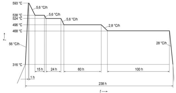
Figure E.1 — Recommended procedure for the step cooling test
Annex F (informative) Changes to the previous version EN 10028-2:2009
- the normative references have been revised;
- the option to agree thicknesses greater as those stated in the standard and the corresponding footnotes in Tables 3 and 4 have been deleted;
- EN 1011-1 and 2 have been moved from the bibliography to the normative references;
- the marking of text passages with one or two dots has been deleted;
- the cross references in the standard have been updated;
- the example for ordering has been revised;
- the steel grade 16Mo3 has been included in subclause 8.2.2 concerning normalized forming;
- the note in sub-clause 8.2.3 has been deleted;
- the values in Table B.1, Annex B have been revised;
- the note in 8.2.4 has been moved to Annex B;
- the correlation in Annex ZA between the clause of this European Standard and the essential requirements of the Directive 2014/68/EU have been updated;
- clarifications on various technical requirements.
Annex ZA (informative) Relationship between this European Standard and the Essential Requirements of European Directive 2014/68/EU aimed to be covered
This European Standard has been prepared under a Commission's standardization request M/071 to provide one voluntary means of conforming to Essential Requirements of Directive 2014/68/EU.
Once this standard is cited in the Official Journal of the European Union under that Directive, compliance with the normative clauses of this standard given in Table ZA.1 confers, within the limits of the scope of this standard, a presumption of conformity with the corresponding Essential Requirements of Directive 2014/68/EU, and associated EFTA regulations.
| Requirements of Directive 2014/68/EU | Clause(s)/subclause(s) of this EN | Remarks/Notes |
|---|---|---|
| 4.1a | 8.4 and Table 3 | Appropriate material properties |
| 4.1d | 8.2 and 8.5 | Suitable for the processing procedures |
| 4.3 | 9.1 | Inspection documentation |
WARNING 1 — Presumption of conformity stays valid only as long as a reference to this European Standard is maintained in the list published in the Official Journal of the European Union. Users of this standard should consult frequently the latest list published in the Official Journal of the European Union.
WARNING 2 — Other Union legislation may be applicable to the product(s) falling within the scope of this standard.
Bibliography
[1] EN 10020, Definition and classification of grades of steel
[2] EN 10314, Method for the derivation of minimum values of proof strength of steel at elevated temperatures
[3] ISO 6303, Pressure vessel steels not included in ISO 2604, Parts 1 to 6 — Derivation of long-time stress rupture properties
[4] NACE/TM 0284, Evaluation of pipeline and pressure vessels steels for resistance to hydrogen induced cracking
扫码下载
随时随地查询现货