Hot rolled products of structural steels – Part 6: Technical delivery conditions for flat products of high yield strength structural steels in the quenched and tempered condition
(Supersedes EN 10025-6:2004+A1:2009)
European foreword
This document (EN 10025-6:2019) has been prepared by Technical Committee CEN/TC 459/SC 3 "Structural steels other than reinforcements", the secretariat of which is held by DIN.
This European Standard shall be given the status of a national standard, either by publication of an identical text or by endorsement, at the latest by February 2020 and conflicting national standards shall be withdrawn at the latest by February 2020.
Attention is drawn to the possibility that some of the elements of this document may be the subject of patent rights. CEN shall not be held responsible for identifying any or all such patent rights.
This document supersedes EN 10025-6:2004+A1:2009.
This document consists of the following parts, under the general title Hot rolled products of structural steels:
- Part 1: General technical delivery conditions
- Part 2: Technical delivery conditions for non-alloy structural steels
- Part 3: Technical delivery conditions for normalized/normalized rolled weldable fine grain structural steels
- Part 4: Technical delivery conditions for thermomechanical rolled weldable fine grain structural steels
- Part 5: Technical delivery conditions for structural steels with improved atmospheric corrosion resistance
- Part 6: Technical delivery conditions for flat products of high yield strength structural steels in the quenched and tempered condition
For a short transition period there will be a coexistence of EN 10025-1:2004 with EN 10025-2:2019 to EN 10025-6:2019, since the new EN 10025-1 has to fulfil the requirements of the CPR and will therefore be published later. For this short transition period up‑to‑the publication of the next edition of part 1 the following is to be taken into account for EN 10025-1:2004:
- a) all dated and undated references to EN 10025-1:2004 to EN 10025-6:2004 are unchanged to this version with following exception: In 9.2.2.1 the references are 8.3.1 and 8.3.2 instead of 8.4.1 and 8.4.2;
- b) Clauses 5, 12 and 13 of EN 10025-1:2004 are no longer relevant.
The main changes with respect to the previous edition are listed below:
- a) part 6 is now a stand‑alone standard for technical delivery conditions including the preparation of samples and test pieces, the test methods, the marking, labelling and packaging and the drawings;
- b) for applications under the CPR this document and part 1 are used together;
- c) requirements for elements not defined were added to 7.2.1 and 7.2.2;
- d) Option 33 was added, Option 3 was renumbered to Option 24 and Option 9 was deleted;
- e) Si‑content in 7.2.4 was changed;
- f) 7.4.3 concerning hot‑dip zinc coating was modified;
- g) in Tables 3 and 4 the values were extended for thicknesses up to 200 mm;
- h) references were updated and document editorial revised.
According to the CEN‑CENELEC Internal Regulations, the national standards organisations of the following countries are bound to implement this European Standard: Austria, Belgium, Bulgaria, Croatia, Cyprus, Czech Republic, Denmark, Estonia, Finland, Republic of North Macedonia, France, Germany, Greece, Hungary, Iceland, Ireland, Italy, Latvia, Lithuania, Luxembourg, Malta, Netherlands, Norway, Poland, Portugal, Romania, Serbia, Slovakia, Slovenia, Spain, Sweden, Switzerland, Turkey and the United Kingdom.
1 Scope
This document specifies technical delivery conditions for flat products of high yield strength alloy special steels. The grades and qualities are given in Tables 1 to 3 (chemical composition) and Tables 4 to 6 (mechanical properties) and are supplied in the quenched and tempered condition.
The steels specified in this document are applicable to hot‑rolled flat products with a minimum nominal thickness of 3 mm and a maximum nominal thickness of 200 mm for grades S460, S500, S550, S620 and S690, a maximum nominal thickness of 125 mm for grades S890 and S960, in steels which, after quenching and tempering, have a specified minimum yield strength of 460 MPa to 960 MPa.
2 Normative references
The following documents are referred to in the text in such a way that some or all of their content constitutes requirements of this document. For dated references, only the edition cited applies. For undated references, the latest edition of the referenced document (including any amendments) applies.
- EN 1011-2, Welding — Recommendations for welding of metallic materials — Part 2: Arc welding of ferritic steels
- EN 10020:2000, Definition and classification of grades of steel
- EN 10021, General technical delivery conditions for steel products
- EN 10025-1, Hot rolled products of structural steels — Part 1: General technical delivery conditions
- EN 10027-1, Designation systems for steels — Part 1: Steel names
- EN 10027-2, Designation systems for steels — Part 2: Numerical system
- EN 10029, Hot‑rolled steel plates 3 mm thick or above — Tolerances on dimensions and shape
- EN 10048, Hot rolled narrow steel strip — Tolerances on dimensions and shape
- EN 10051, Continuously hot‑rolled strip and plate/sheet cut from wide strip of non‑alloy and alloy steels — Tolerances on dimensions and shape
- EN 10079, Definition of steel products
- EN 10160, Ultrasonic testing of steel flat product of thickness equal or greater than 6 mm (reflection method)
- EN 10163-1, Delivery requirements for surface condition of hot‑rolled steel plates, wide flats and sections — Part 1: General requirements
- EN 10163-2, Delivery requirements for surface condition of hot‑rolled steel plates, wide flats and sections — Part 2: Plate and wide flats
- EN 10164, Steel products with improved deformation properties perpendicular to the surface of the product — Technical delivery conditions
- EN 10168, Steel products — Inspection documents — List of information and description
- EN 10204, Metallic products — Types of inspection documents
- EN 10315, Routine method for analysis of high alloy steel by X‑ray Fluorescence Spectrometry (XRF) by using a near by technique
- CR 10320, Optical emission analysis of low alloy steels (routine method) — Method for determination of C, Si, S, P, Mn, Cr, Ni and Cu
- EN ISO 148-1, Metallic materials — Charpy pendulum impact test — Part 1: Test method (ISO 148-1)
- EN ISO 377, Steel and steel products — Location and preparation of samples and test pieces for mechanical testing (ISO 377)
- EN ISO 2566-1, Steel — Conversion of elongation values — Part 1: Carbon and low alloy steels (ISO 2566-1)
- EN ISO 6892-1:2016, Metallic materials — Tensile testing — Part 1: Method of test at room temperature (ISO 6892-1:2016)
- EN ISO 14713-2:2009, Zinc coatings — Guidelines and recommendations for the protection against corrosion of iron and steel in structures — Part 2: Hot dip galvanizing (ISO 14713-2:2009)
- EN ISO 14284, Steel and iron — Sampling and preparation of samples for the determination of chemical composition (ISO 14284)
- EN ISO 15350, Steel and iron — Determination of total carbon and sulfur content — Infrared absorption method after combustion in an induction furnace (routine method) (ISO 15350)
3 Terms and definitions
For the purposes of this document, the terms and definitions given in EN 10079 and the following apply. ISO and IEC maintain terminological databases for use in standardization at the following addresses:
IEC Electropedia: available at http://www.electropedia.org/
ISO Online browsing platform: available at http://www.iso.org/obp
3.1 quenching
operation which consists of cooling a ferrous product more rapidly than in still air
3.2 tempering
heat treatment applied to a ferrous product generally after quench hardening or other heat treatment to bring the properties to the required level
Note 1 to entry: Tempering consists of heating to specific temperatures (< Acl) and soaking one or more times followed by cooling at an appropriate rate.
4 Classification and designation
4.1 Classification
4.1.1 Main quality classes
The steel grades specified in this document shall be classified as alloy special steels according to EN 10020.
4.1.2 Grades and qualities
This document specifies seven steel grades. They differ in their minimum yield strength at room temperature.
All steel grades may be supplied in the following qualities as specified at the time of the order:
- with specified minimum values of impact energy at temperatures not lower than –20°C, designated as Q;
- with specified minimum values of impact energy at temperatures not lower than –40°C, designated as QL;
- with specified minimum values of impact energy at temperatures not lower than –60°C, designated as QL1.
4.2 Designation
4.2.1 For the steel grades covered by this document the steel names shall be allocated in accordance with EN 10027‑1; the steel numbers shall be allocated in accordance with EN 10027‑2.
4.2.2 The designation shall consist of:
- the number of this document (EN 10025‑6);
- the steel name or the steel number;
- the steel name consisting of: the symbol S (for structural steel); the indication of the minimum specified yield strength for thickness ≤ 50 mm expressed in MPa; the delivery condition Q; the capital letter L or L1 for the quality with specified minimum values of impact energy at temperatures not lower than –40°C or –60°C.
EXAMPLE Structural steel (S) quenched and tempered (Q), with a specified minimum yield strength at room temperature of 460 MPa and with a specified minimum of impact energy at –40°C (L):
EN 10025‑6 – S460QL
Or
EN 10025‑6 – 1.8906
5 Information to be supplied by the purchaser
5.1 Mandatory information
The following information shall be supplied by the purchaser at the time of the order:
- a) quantity to be delivered;
- b) product form and the number of the standard for dimensions and tolerances (see 2.2);
- c) nominal dimensions and tolerances on dimensions and shape (see 7.7.1);
- d) steel designation (see 4.2.2);
- e) additional requirements of inspection and testing and all required options (see 5.2 and Clause 13);
- f) type of inspection document according to EN 10204 (see 8.1);
5.2 Options
A number of options are specified in Clause 13. In the event that the purchaser does not indicate his wish to implement any of these options, the supplier shall supply in accordance with the basic specification, see 5.1 a) to d) and f).
6 Manufacturing process
6.1 Steel making process
The steel making process is at the discretion of the manufacturer with the exclusion of the open hearth (Siemens‑Martin) process.
See Option 1, Clause 13 (details of manufacturing process).
6.2 Deoxidation and grain structure
Steels of EN 10025‑6 shall:
- be fully killed;
- have a fine grain structure;
- contain nitrogen binding elements in amounts sufficient to bind the available nitrogen (for example min. 0.020% total aluminium). The usual guideline is a minimum aluminium to nitrogen ratio of 2:1, when no other nitrogen binding elements are present. Such other elements and their content (% mass) shall be reported in the inspection document (see Table 1).
6.3 Delivery conditions
The products shall be supplied in the quenched and tempered condition (Q) as defined in Clause 3.
NOTE Direct quenching after hot‑rolling followed by tempering is considered equivalent to conventional quenching and tempering.
7 Requirements
7.1 General
The requirements in 7.2 and 7.3 apply for sampling, preparation of test pieces and testing specified in Clauses 9 and 10.
7.2 Chemical composition
7.2.1 The chemical composition determined by heat analysis shall comply with the specified values of Table 1.
For elements not defined in the table for the chemical composition for heat analysis, limit values of Table 1 of EN 10020:2000 shall apply as maximum values.
7.2.2 The upper limits applicable for the product analysis are given in Table 2. The product analysis shall be carried out when specified at the time of the order.
See Option 2, Clause 13 (product analysis).
7.2.3 The maximum carbon equivalent values based on the heat analysis, given in Table 3 shall apply.
For determining the carbon equivalent value the following IIW (International Institute of Welding) formula shall be used:
CEV = C + Mn/6 + (Cr + Mo + V)/5 + (Ni + Cu)/15
7.2.4 When products are supplied with a control on Si e.g. for hot‑dip zinc‑coating so that there could be a need to increase the content of other elements like C and Mn to achieve the required tensile properties, the maximum carbon equivalent values of Table 3 shall be increased as follows:
- for Si ≤ 0,04%, increase the value of the CEV by 0,02;
- for Si ≤ 0,25%, increase the value of the CEV by 0,01.
| Grade | Quality | C | Si | Mn | P | S | N | B | Cr | Cu | Mo | Nb | Ni | Ti | V | Zr | |
|---|---|---|---|---|---|---|---|---|---|---|---|---|---|---|---|---|---|
| % max. | % max. | % max. | % max. | % max. | % max. | % max. | % max. | % max. | % max. | % max. b |
% max. | % max. b |
% max. b |
% max. b |
|||
| All grades | (no symbol) | 0,20 | 0,80 | 1,70 | 0,025 | 0,015 | 0,015 | 0,005 0 | 1,50 | 0,50 | 0,70 | 0,06 | 4,0 | 0,05 | 0,12 | 0,15 | |
| L | 0,020 | 0,010 | |||||||||||||||
| L1 | 0,020 | 0,010 | |||||||||||||||
|
a Depending on the thickness of the product and the manufacturing conditions, the manufacturer may add to the steel one or several alloying elements up to the maximum values given in order to obtain the specified properties (see 7.2.1). b Nitrogen binding elements shall be in amounts sufficient to bind the nitrogen (see 6.2). |
|||||||||||||||||
| Grade | Quality | C | Si | Mn | P | S | N | B | Cr | Cu | Mo | Nb | Ni | Ti | V | Zr | |
|---|---|---|---|---|---|---|---|---|---|---|---|---|---|---|---|---|---|
| % max. | % max. | % max. | % max. | % max. | % max. | % max. | % max. | % max. | % max. | % max. b |
% max. | % max. b |
% max. b |
% max. b |
|||
| All grades | (no symbol) | 0,22 | 0,86 | 1,80 | 0,030 | 0,017 | 0,016 | 0,006 0 | 1,60 | 0,55 | 0,74 | 0,07 | 4,10 | 0,07 | 0,14 | 0,17 | |
| L | 0,025 | 0,012 | |||||||||||||||
| L1 | 0,025 | 0,012 | |||||||||||||||
|
a Depending on the thickness of the product and the manufacturing conditions, the manufacturer may add to the steel one or several alloying elements up to the maximum values given in order to obtain the specified properties (see 7.2.2). b Nitrogen binding elements shall be in amounts sufficient to bind the nitrogen (see 6.2). |
|||||||||||||||||
| Designation | Maximum CEV in % for nominal product thickness in mm | ||||
|---|---|---|---|---|---|
| Steel name | Steel number | ≤ 50 | > 50 ≤ 100 | > 100 ≤ 125 | > 125 ≤ 200 |
| S460Q | 1.8908 | 0,47 | 0,48 | 0,50 | 0,50 |
| S460QL | 1.8906 | ||||
| S460QL1 | 1.8916 | ||||
| S500Q | 1.8924 | 0,47 | 0,70 | 0,70 | 0,70 |
| S500QL | 1.8909 | ||||
| S500QL1 | 1.8984 | ||||
| S550Q | 1.8904 | 0,65 | 0,77 | 0,83 | 0,83 |
| S550QL | 1.8926 | ||||
| S550QL1 | 1.8986 | ||||
| S620Q | 1.8914 | 0,65 | 0,77 | 0,83 | 0,83 |
| S620QL | 1.8927 | ||||
| S620QL1 | 1.8987 | ||||
| S690Q | 1.8931 | 0,65 | 0,77 | 0,83 | 0,83 |
| S690QL | 1.8928 | ||||
| S690QL1 | 1.8988 | ||||
| S890Q | 1.8940 | 0,72 | 0,82 | 0,83 | - |
| S890QL | 1.8983 | ||||
| S890QL1 | 1.8925 | ||||
| S960Q | 1.8941 | 0,82 | 0,85 | 0,85 | - |
| S960QL | 1.8933 | ||||
| S960QL1 | 1.8934 | ||||
| a Max. CEV is increased for Option 5 (Clause 13), see 7.2.4. | |||||
7.3 Mechanical properties
7.3.1 General
7.3.1.1 Under the inspection and testing conditions as specified in Clauses 8, 9 and 10 and in the delivery condition as specified in 6.3 the mechanical properties shall comply with the values given in Tables 4, 5 and 6.
The maximum stress‑relief temperature should be at least 30°C below the tempering temperature and not be held for more than 1 h. As this temperature is normally not known in advance it is recommended that the purchaser if he intends to perform a stress relief treatment to contact the steel producer. If the purchaser intends to stress relief the products at higher temperatures or for longer times than mentioned above the minimum values of the mechanical properties after such a treatment should be agreed upon at the time of the order.
7.3.1.2 For the products specified in this document the nominal thickness applies.
| Designation | Minimum yield strength ReH MPa Nominal thickness mm |
Tensile strength Rm MPa Nominal thickness mm |
Minimum percentage elongation after fracture % L₀ = 5,65 √S₀ |
|||||||
|---|---|---|---|---|---|---|---|---|---|---|
| Steel name | Steel number | ≥ 3 ≤ 50 | > 50 ≤ 100 | > 100 ≤ 125 | > 125 ≤ 200 | ≥ 3 ≤ 50 | > 50 ≤ 100 | > 100 ≤ 125 | > 125 ≤ 200 | |
| S460Q | 1.8908 | 460 | 440 | 400 | 550 to 720 | 500 to 670 | 17 | |||
| S460QL | 1.8906 | |||||||||
| S460QL1 | 1.8916 | |||||||||
| S500Q | 1.8924 | 500 | 480 | 440 | 590 to 770 | 540 to 720 | 17 | |||
| S500QL | 1.8909 | |||||||||
| S500QL1 | 1.8984 | |||||||||
| S550Q | 1.8904 | 550 | 530 | 490 | 640 to 820 | 590 to 770 | 16 | |||
| S550QL | 1.8926 | |||||||||
| S550QL1 | 1.8986 | |||||||||
| S620Q | 1.8914 | 620 | 580 | 560 | 700 to 890 | 650 to 830 | 15 | |||
| S620QL | 1.8927 | |||||||||
| S620QL1 | 1.8987 | |||||||||
| S690Q | 1.8931 | 690 | 650 | 630 | 770 to 940 | 760 to 930 | 710 to 900 | 14 | ||
| S690QL | 1.8928 | |||||||||
| S690QL1 | 1.8988 | |||||||||
| S890Q | 1.8940 | 890 | 830 | 830 | - | 940 to 1 100 | 880 to 1 100 | 880 to 1 100 | - | 11 |
| S890QL | 1.8983 | |||||||||
| S890QL1 | 1.8925 | |||||||||
| S960Q | 1.8941 | 960 | 850 | 850 | - | 980 to 1 150 | 900 to 1 100 | 900 to 1 100 | - | 10 |
| S960QL | 1.8933 | |||||||||
| S960QL1 | 1.8934 | |||||||||
| Designation | Minimum values of impact energy KV2 in J at test temperatures, in °C |
||||
|---|---|---|---|---|---|
| Steel name | Steel number | 0 | - 20 | - 40 | - 60 |
| S460Q | 1.8908 | 40 | 30 | - | - |
| S500Q | 1.8924 | ||||
| S550Q | 1.8904 | ||||
| S620Q | 1.8914 | ||||
| S690Q | 1.8931 | ||||
| S890Q | 1.8940 | ||||
| S960Q | 1.8941 | ||||
| S460QL | 1.8906 | 50 | 40 | 30 | - |
| S500QL | 1.8909 | ||||
| S550QL | 1.8926 | ||||
| S620QL | 1.8927 | ||||
| S690QL | 1.8928 | ||||
| S890QL | 1.8983 | ||||
| S960QL | 1.8933 | ||||
| S460QL1 | 1.8916 | 60 | 50 | 40 | 30 |
| S500QL1 | 1.8984 | ||||
| S550QL1 | 1.8986 | ||||
| S620QL1 | 1.8987 | ||||
| S690QL1 | 1.8988 | ||||
| S890QL1 | 1.8925 | ||||
| S960QL1 | 1.8934 | ||||
| For subsized specimens the minimum values shall be reduced in direct proportion to the cross-sectional area of the test piece. | |||||
| a Exceptions due to product size restrictions see 9.2.3.3. | |||||
7.3.2 Impact properties
7.3.2.1 The verification of the impact energy value shall be carried out, unless otherwise agreed upon (see 7.3.2.2 and 7.3.2.3) with longitudinal test pieces for:
- quality Q at –20°C
- quality QL at –40°C
- quality QL1 at –60°C
7.3.2.2 Another temperature (given in Tables 5 and 6) may be agreed upon at the time of the order.
See Option 24, Clause 13 (Agreement on another impact test temperature).
7.3.2.3 If agreed upon at the time of the order the impact properties shall be verified on transverse V‑notch test pieces instead of longitudinal test pieces with minimum values as given in Table 6.
See Option 30, Clause 13 (Impact properties verified on transverse test pieces).
| Designation | Minimum values of impact energy KV2 in J at test temperatures, in °C |
||||
|---|---|---|---|---|---|
| Steel name | Steel number | 0 | - 20 | - 40 | - 60 |
| S460Q | 1.8908 | 30 | 27 | - | - |
| S500Q | 1.8924 | ||||
| S550Q | 1.8904 | ||||
| S620Q | 1.8914 | ||||
| S690Q | 1.8931 | ||||
| S890Q | 1.8940 | ||||
| S960Q | 1.8941 | ||||
| S460QL | 1.8906 | 35 | 30 | 27 | - |
| S500QL | 1.8909 | ||||
| S550QL | 1.8926 | ||||
| S620QL | 1.8927 | ||||
| S690QL | 1.8928 | ||||
| S890QL | 1.8983 | ||||
| S960QL | 1.8933 | ||||
| S460QL1 | 1.8916 | 40 | 35 | 30 | 27 |
| S500QL1 | 1.8984 | ||||
| S550QL1 | 1.8986 | ||||
| S620QL1 | 1.8987 | ||||
| S690QL1 | 1.8988 | ||||
| S890QL1 | 1.8925 | ||||
| S960QL1 | 1.8934 | ||||
| For subsized specimens the minimum values shall be reduced in direct proportion to the cross-sectional area of the test piece. | |||||
| a Exceptions due to product size restrictions see 9.2.3.3. | |||||
7.3.2.4 If specified at the time of the order on each heat treatment unit the impact properties only or the impact properties and the tensile properties shall be verified.
See Option 13, Clause 13 (For each heat treatment unit impact properties only to be verified).
See Option 14, Clause 13 (For each heat treatment unit impact and tensile properties to be verified).
7.3.3 Improved deformation properties perpendicular to the surface
If agreed upon at the time of the order the products shall comply with one of the requirements of EN 10164.
See Option 4, Clause 13 (Deformation properties perpendicular to the surface).
7.4 Technological properties
7.4.1 Weldability
The steels specified in this document do not have unlimited suitability for the various welding processes, since the behaviour of a steel during and after welding depends not only on the material but also on the dimensions and shape and on the manufacturing and service conditions of the components.
General requirements for arc welding of the steels specified in this document shall be as given in EN 1011‑2.
NOTE With increasing product thickness and strength level cold cracking can occur. Cold cracking is caused by the following factors in combination:
- the amount of diffusible hydrogen in the weld metal;
- a brittle structure of the heat affected zone;
- significant tensile stress concentrations in the welded joint.
7.4.2 Formability and flame straightening
7.4.2.1 General
Recommendations regarding hot forming, cold forming and flame‑straightening are laid out in CEN/TR 10347.
7.4.2.2 Hot‑forming
Hot forming is not recommended for quenched and tempered steels as the necessary heat treatment after hot forming is very difficult to reproduce.
7.4.2.3 Cold formability
7.4.2.3.1 General
NOTE Cold forming leads to reduction in the ductility. Furthermore it is important to draw the attention to the risk of brittle fracture in connection with hot‑dip zinc coating.
7.4.2.3.2 Flangeability
If specified at the time of the order plates and wide flats with a nominal thickness ≤ 16 mm are suitable for flanging without cracking with the indicative values for the inside minimum bend radii for cold forming as given in Annex B.
See Option 11, Clause 13 (Flangeability without cracking).
7.4.3 Hot‑dip zinc‑coating
EN ISO 1461 should be used to specify coating requirements. EN ISO 14713‑2 provides further guidance, including information on the influence of various factors, including steel chemical composition, on the coating formation.
Option 5, Clause 13 can be used to order steels with a chemical composition required for hot‑dip zinc coating. When option 5 is implemented, the purchaser and manufacturer shall agree to a steel composition (heat analysis) of silicon and phosphorous according to either Category A (or steels satisfying the formula Si ≤ 0,03% and Si + 2,5P ≤ 0,09%) or Category B (limited to 0,14% ≤ Si ≤ 0,25%) or Category D (limited to 0,25% < Si ≤ 0,35%) with required values as cited by the ranges given in EN ISO 14713‑2:2009, Table 1, column 2.
NOTE 1 EN ISO 14713‑2:2009, Table 1, gives guidance on typical coating characteristics associated with certain steel compositions on the basis of the surface composition of silicon and phosphorous.
The maximum carbon equivalent shall be increased by 0,02 or by 0,01 (see 7.2.4).
NOTE 2 Products quenched in water can be susceptible to stress corrosion cracking after hot‑dip zinc‑coating.
See Option 5, Clause 13 (Chemical composition for hot dip zinc coating).
In some cases steels above S460 may be sensitive to cracking during galvanizing and therefore special care should be taken.
7.5 Surface properties
EN 10163‑1 and EN 10163‑2 shall apply for the permissible surface discontinuities for plates and wide flats and for the repair of surface defects by grinding and/or welding. Class A, subclass 1 of EN 10163‑2 shall apply, class B regarding grinding or subclasses 2 or 3 regarding repair by welding can be agreed upon at the time of the order.
See Option 15, Clause 13 (Other surface class for plates and wide flats).
7.6 Internal soundness
Ultrasonic testing may be agreed upon at the time of the order and shall comply with 10.3.
See Option 6, Clause 13 (Ultrasonic testing for flat products).
7.7 Tolerances on dimensions and shape, mass
7.7.1 Dimensions, tolerances on dimensions and shape shall be in accordance with the requirements given in the order by reference to following standards: EN 10029, EN 10048, and EN 10051.
For hot rolled plate tolerances the basic requirements shall be in accordance with EN 10029, including thickness tolerances to class A, unless otherwise agreed upon at the time of the order.
See Option 18, Clause 13 (For plates other thickness tolerance than class A).
For plates cut from continuously hot rolled strip, the thickness tolerances shall be in accordance with EN 10051, unless otherwise agreed upon at the time of the order.
See Option 34, Clause 13 (For plates cut from strip thickness tolerances according to EN 10029).
7.7.2 The nominal mass shall be determined from the nominal dimensions using a volumetric mass of 7 850 kg/m³.
8 Inspection
8.1 Type of inspection and inspection document
The products shall be delivered with specific inspection and testing to indicate compliance with the order and this document. The manufacturer shall obtain from the purchaser which of the inspection documents specified in EN 10204 is required.
NOTE Some application standards, e.g. EN 1090‑2, require particular inspection documents according to EN 10204.
Unless otherwise agreed upon, steel grades of this standard are delivered with CE marking and they shall not only fulfil these technical delivery conditions, but the requirements of EN 10025‑1, too.
It can be agreed upon at the time of enquiry and order to abstain from CE‑marking, see Option 33, Clause 13, in this case EN 10025‑1 does not apply.
See Option 33, Clause 13 (no application of CE‑marking).
8.2 Content of inspection document
The inspection document shall include, in accordance with EN 10168, the following codes and/or information, where applicable:
| Code | Description |
|---|---|
| A | commercial transactions and parties involved; |
| B | description of products to which the inspection document applies; |
| C00‑C03 | identification of the sample, location of the sample, direction of the test pieces, test temperature; |
| C10‑C13 | shape of the test piece, yield or proof strength, tensile strength, elongation after fracture; |
| C40‑C43 | type of test piece, width of test piece, individual values, mean value; |
| C70‑C92 | steelmaking process, chemical composition; |
| D | other tests; |
| Z | validation. |
8.3 Tests to be carried out
8.3.1 The following tests shall be carried out:
- the heat analysis;
- the tensile test;
- the impact test with thickness limitations as specified in 9.2.3.3.
8.3.2 At the time of the order the following additional tests can be agreed upon (see also Clause 13):
- a) the product analysis, see 7.2.2 and Option 2, Clause 13;
- b) for all products the impact test at another temperature, see 7.3.2.2 and Option 24, Clause 13, or/and on transverse test pieces, see 7.3.2.3 and Option 30, Clause 13.
9 Frequency of testing and preparation of samples and test pieces
9.1 Frequency of testing
9.1.1 Chemical analysis
The heat analysis shall be determined once per cast. If a product analysis has been agreed upon at the time of enquiry and order, the purchaser shall specify the frequency if not once per cast.
9.1.2 Mechanical tests
The verification of the mechanical properties (tensile strength, yield strength, impact energy and elongation) shall be by test unit(s) from within each cast.
Unless otherwise specified (see 7.3.2.4) for verifying the mechanical properties the test unit shall be 60 tonnes or part thereof. The test unit shall contain products of the same form and grade and of the same thickness range for the yield strength requirement as given in Table 4. The nominal thickness of a product within the test unit shall not deviate more than 5 mm from that of the sample product.
The following samples shall be taken from one sample product of each test unit:
- one sample for tensile testing;
- one sample sufficient for one set of six impact test pieces.
9.2 Preparation of samples and test pieces
9.2.1 Selection and preparation of samples for chemical analysis
The selection and preparation of samples for product analysis shall be in accordance with EN ISO 14284.
9.2.2 Location of samples and orientation of test pieces for mechanical tests
The samples shall be taken from any product of the test unit, from the location in the product as shown in Annex A.
Additionally for plates, sheet, wide strip and wide flats the samples shall be taken so that the axes of the test pieces are approximately midway between the edge and centre line of the products.
For wide strip the sample shall be taken at an adequate distance from the end of the product.
For narrow strip (< 600 mm wide) the sample shall be taken at an adequate distance from the end of the coil and at one third of the width.
9.2.3 Preparation of test pieces for mechanical tests
9.2.3.1 General
The requirements of EN ISO 377 shall apply.
9.2.3.2 Preparation of tensile test pieces
The requirements of EN ISO 6892‑1 shall apply.
For flat products of nominal thickness > 30 mm a round test piece may be used with the longitudinal axis at ¼ thickness, if a testing machine with an adequate capacity is not available. In cases of dispute, the total thickness of the plate shall be subdivided in equal thick flat test pieces. The average of the individual results of the mechanical tests shall be valid.
9.2.3.3 Preparation of impact test pieces
V‑notch test pieces shall be machined and prepared in accordance with EN ISO 148‑1. In addition the following requirements apply for flat products:
- for nominal thicknesses 12 < t < 40 mm, standard 10 mm × 10 mm test pieces shall be machined in such a way that one side is not further away than 2 mm from a rolled surface,
- for nominal thicknesses ≥ 40 mm impact test pieces shall be taken from ¼ t position for plates;
- for nominal thicknesses ≤ 12 mm, when test pieces with reduced widths are used, the largest width possible has to be chosen;
- for nominal thickness < 6 mm no impact tests are required.
9.3 Identification of samples and test pieces
Samples and test pieces shall be marked so that the original products and their location and orientation in the product are known.
10 Test methods
10.1 Chemical analysis
Test methods shall be in accordance with EN 10315, EN ISO 15350 or CR 10320 depending on the elements to be analysed and their content. The choice of a suitable physical or chemical analytical method for the analysis shall be at the discretion of the manufacturer. In cases of dispute, the method used shall be agreed upon taking into account CEN/TR 10261.
For the heat analysis the manufacturer shall report values of all elements defined in Table 1 for the steel grade concerned for each cast as well as of the elements for determining the carbon equivalent value.
For the product analysis, if not otherwise agreed upon, the manufacturer shall report values of all elements defined in Table 2 for the steel grade concerned, see Option 2 (Clause 13).
10.2 Mechanical tests
10.2.1 Tensile test
The tensile test shall be carried out in accordance with EN ISO 6892‑1. The manufacturer may choose between method A or B specified in EN ISO 6892‑1 for the tensile test.
For the specified yield strength the upper yield strength (ReH) shall be determined.
If a yield phenomenon is not present, the 0.2% proof strength (Rp0,2) shall be determined.
Test pieces may be non‑proportional but in cases of dispute proportional test pieces having a gauge length L0 = 5,65√S0 shall be used.
For flat products with a nominal thickness < 3 mm the test pieces shall always have a gauge length L0 = 80 mm and a width of 20 mm (test piece number 2 EN ISO 6892‑1:2016, Annex B).
For normal testing, for reasons of economy, test pieces of a constant measuring length may be used provided the result obtained for elongation after fracture is converted by the formula in EN ISO 2566‑1.
NOTE In the scope of EN ISO 2566‑1, quenched and tempered steels are excluded. In practice the figures of EN ISO 2566‑1 can be used.
10.2.2 Impact test
The impact test shall be carried out in accordance with EN ISO 148‑1 on V‑notch specimen using 2 mm striker.
The average value of the three test results shall meet the specified requirement. One individual value may be below the minimum average value specified, provided that it is not less than 70% of that value.
Three additional test pieces shall be taken from the same sample in accordance with 9.1.2 and tested in any one of the following cases:
- if the average of three impact values is lower than the minimum average value specified;
- if the average value meets the specified requirement, but two individual values are lower than the minimum average value specified;
- if any one value is lower than 70% of the minimum average value specified.
The average value of the six tests shall be not less than the minimum average value specified. Not more than two of the individual values may be lower than the minimum average value specified and not more than one may be lower than 70% of this value.
10.3 Ultrasonic testing
If specified at the time of the order (see 7.6), ultrasonic testing shall be carried out for flat products in nominal thicknesses ≥ 6 mm, except for hot rolled strip and plate cut from strip in accordance with EN 10160.
10.4 Retests
The retests shall be in accordance with EN 10021.
In the case of strip, retests on a rejected coil shall be carried out after the cutting of an additional longitudinal section of sufficient length to remove the coil end effect with a maximum of 20 m.
11 Marking, labelling, packaging
11.1 The products shall be legibly marked using methods such as painting, stamping, laser marking, bar coding, durable adhesive labels or attached tags with the following:
- the grade, the quality and if applicable the delivery condition indicated by its abridged designation;
- a number by which the cast and if applicable the sample can be identified;
- the manufacturer's name or trademark.
The type of marking may be specified at the time of the order.
See Option 10, Clause 13 (special type of marking).
NOTE 1 Where the option for hot dip galvanizing is chosen (see Clause 13) the marking methods and materials used can be agreed upon in order to avoid interference with preparation for hot dip galvanizing (see EN ISO 14713‑2).
The mark of the external inspection representative may be marked (where applicable).
NOTE 2 This depends on the type of inspection document (see 8.1).
In addition if specified at the time of the order there shall be either no die stamping or only die stamping in positions indicated by the purchaser.
11.2 Marking shall be at a position close to one end of each product or on the end cut face at the manufacturer's discretion.
11.3 Where products are supplied in securely tied bundles the marking shall be on a label attached to the bundle or on the top product of the bundle.
12 Complaints
Any complaints shall be dealt with in accordance with EN 10021.
13 Options
A list of options for parts 2 to 6 is given in Annex C for information. The following options (see 5.2) apply for this part:
- 1 The steel making process shall be indicated (see 6.1).
- 2 Product analysis shall be carried out; the number of samples shall be as agreed upon (see 7.2.2 and 9.1.1).
- 4 Products shall comply with one of the improved properties perpendicular to the surface of EN 10164 (see 7.3.3).
- 5 The product shall have a chemical composition required for hot‑dip zinc‑coating (see 7.4.3).
- 6 For flat products in nominal thickness ≥ 6 mm, except for hot rolled strip and plate cut from strip, the freedom from internal defects shall be verified in accordance with EN 10160 (see 7.6 and 10.3).
- 10 The type of marking required (see Clause 11).
- 11 Sheet, plate, strip and wide flats with a nominal thickness ≤ 16 mm shall be suitable for flanging without cracking (see 7.4.2.3.2).
- 13 For each heat treatment unit the impact properties only shall be verified (see 7.3.2.4).
- 14 For each heat treatment unit the impact properties and the tensile properties shall be verified (see 7.3.2.4).
- 15 For plates and wide flats the permissible surface discontinuities and for the repair of surface defects by grinding and/or welding another class than class A, subclass 1 of EN 10163‑2 applies (see 7.5).
- 18 For hot rolled plates other tolerances than class A of EN 10029 apply (see 7.7.1).
- 24 At which temperature the impact properties shall be verified (see 7.3.2.2 and 8.3.2).
- 30 The impact properties shall be verified on transverse V‑notch test pieces (see 7.3.2.3 and 8.3.2).
- 31 Die stamping is not allowed or the position for die stamping shall be as indicated by the purchaser (see Clause 11).
- 33 No application of CE‑marking according to EN 10025‑1, and no application of assessment and verification of constancy of performance according to EN 10025‑1, for products, which are not covered by the Construction Product Regulation.
- 34 For plates cut from continuously hot rolled strip thickness tolerances according to EN 10029 apply (see 7.7.1).
Annex A (normative) Location of samples and test pieces
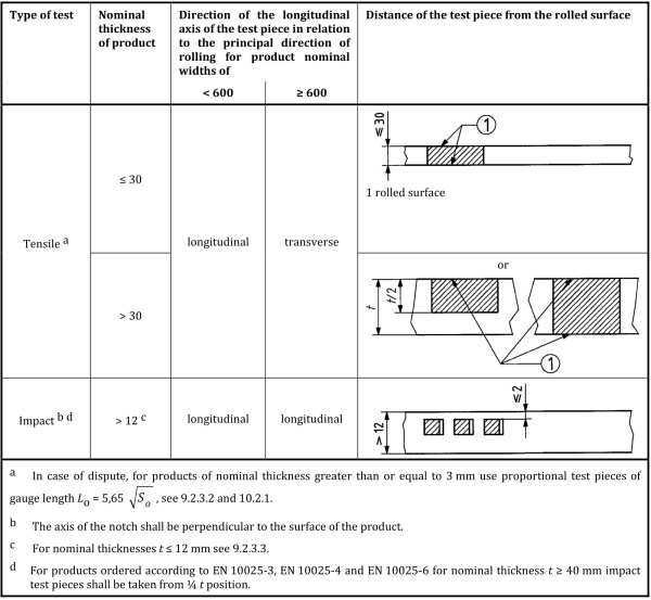
Figure A.1 — Beams, channels, angles, T sections and Z sections
Annex B (informative) Minimum recommended inside bend radii for flanging
| Designation | Minimum recommended inside bend radii for nominal thicknesses (t) 3 ≤ t ≤ 16 mm a | ||
|---|---|---|---|
| Steel name | Steel number | Axis of bend in transverse direction | Axis of bend in longitudinal direction |
| S460Q | 1.8908 | 3,0 t | 4,0 t |
| S460QL | 1.8906 | ||
| S460QL1 | 1.8916 | ||
| S500Q | 1.8924 | ||
| S500QL | 1.8909 | ||
| S500QL1 | 1.8984 | ||
| S550Q | 1.8904 | ||
| S550QL | 1.8926 | 3,0 t | 4,0 t |
| S550QL1 | 1.8986 | 3,0 t | 4,0 t |
| S620Q | 1.8914 | 3,0 t | 4,0 t |
| S620QL | 1.8927 | 3,0 t | 4,0 t |
| S620QL1 | 1.8987 | 3,0 t | 4,0 t |
| S690Q | 1.8931 | 3,0 t | 4,0 t |
| S690QL | 1.8928 | 3,0 t | 4,0 t |
| S690QL1 | 1.8988 | 3,0 t | 4,0 t |
| S890Q | 1.8940 | 4,0 t | 5,0 t |
| S890QL | 1.8983 | ||
| S890QL1 | 1.8925 | ||
| S960Q | 1.8941 | ||
| S960QL | 1.8933 | ||
| S960QL1 | 1.8934 | ||
| a The values are applicable for bend angles ≤ 90°. | |||
Annex C (informative) List of Options of EN 10025‑2 to ‑6
| Number of Option | Options | Part 2 | Part 3 | Part 4 | Part 5 | Part 6 |
|---|---|---|---|---|---|---|
| 1 | Details of manufacturing process | x | x | x | x | x |
| 2 | Product analysis | x | x | x | x | x |
| 3 | Verification of impact properties Part 2: for qualities JR Part 5: for qualities S355 class WP | x | - | - | x | - |
| 4 | Deformation properties perpendicular to the surface | x | x | x | x | x |
| 5 | Chemical composition for hot dip zinc coating | x | x | x | - | x |
| 6 | Ultrasonic testing for flat products | x | x | x | x | x |
| 7 | Ultrasonic testing for sections | x | x | x | x | - |
| 8 | Ultrasonic testing for bars | x | x | x | x | - |
| 9 | - | - | - | - | - | - |
| 10 | Special type of marking | x | x | x | x | x |
| 11 | Flangeability without cracking Part 2: nominal thickness ≤ 30 mm Part 3: nominal thickness ≤ 16 mm Part 4: nominal thickness ≤ 12 mm Part 5: nominal thickness ≤ 20 mm Part 6: nominal thickness ≤ 16 mm | x | x | x | x | x |
| 12 | Roll forming of flat products | x | x | x | - | - |
| 13 | For flat products out of each parent plate or coil impact properties only to be verified. Part 2: for qualities J2 and K2 Part 3 and 4: for all qualities Part 5: for qualities J2, J4, J5 and K2 Part 6: for each heat treatment unit and for all qualities | x | x | x | x | x |
| 14 | For flat products out of each parent plate or coil impact and tensile properties to be verified. Part 2: for qualities J2 and K2 Part 3 and 4: for all qualities Part 5: for qualities J2, J4, J5 and K2 Part 6: for each heat treatment unit and for all qualities | x | x | x | x | x |
| 15 | Other surface class for plates and wide flats | x | x | x | x | x |
| 16 | Other surface class for sections | x | x | x | x | - |
| 17 | Other surface class for bars and rods | x | x | x | x | - |