SPECIFICATION FOR GENERAL REQUIREMENTS FOR ROLLED STRUCTURAL STEEL BARS, PLATES, SHAPES, AND SHEET PILING
(Identical with ASTM Specification A6/A6M-21)
1. Scope
1.1 This general requirements specification covers a group of common requirements that, unless otherwise specified in the applicable product specification, apply to rolled structural steel bars, plates, shapes, and sheet piling covered by each of the following product specifications issued by ASTM:
| ASTM Designation | Title of Specification |
|---|---|
| A36/A36M | Carbon Structural Steel |
| A131/A131M | Structural Steel for Ships |
| A242/A242M | High-Strength Low-Alloy Structural Steel |
| A283/A283M | Low and Intermediate Tensile Strength Carbon Steel Plates |
| A328/A328M | Steel Sheet Piling |
| A514/A514M | High-Yield-Strength, Quenched and Tempered Alloy Steel Plate, Suitable for Welding |
| A529/A529M | High-Strength Carbon-Manganese Steel of Structural Quality |
| A572/A572M | High-Strength Low-Alloy Columbium-Vanadium Structural Steel |
| A573/A573M | Structural Carbon Steel Plates |
| A588/A588M | High-Strength Low-Alloy Structural Steel, up to 50 ksi [345 MPa] Minimum Yield Point, with Atmospheric Corrosion Resistance |
| A633/A633M | Normalized High-Strength Low-Alloy Structural Steel Plates |
| A656/A656M | Hot-Rolled Structural Steel, High-Strength Low-Alloy Plate with Improved Formability |
| A690/A690M | High-Strength Low-Alloy Nickel, Copper, Phosphorus Steel H-Piles and Sheet Piling with Atmospheric Corrosion Resistance for Use in Marine Environments |
| A709/A709M | Structural Steel for Bridges |
| A710/A710M | Precipitation-Strengthened Low-Carbon Nickel-Copper-Chromium-Molybdenum-Columbium Alloy Structural Steel Plates |
| A769/A769M | Carbon and High-Strength Electric Resistance Forgeless Steel Structural Shapes |
| A786/A786M | Hot-Rolled Carbon, Low-Alloy, High-Strength Low-Alloy, and Alloy Steel Floor Plates |
| A827/A827M | Plates, Carbon Steel, for Forging and Similar Applications |
| A829/A829M | Alloy Structural Steel Plates |
| A830/A830M | Plates, Carbon Steel, Structural Quality, Furnished to Chemical Composition Requirements |
| A857/A857M | Steel Sheet Piling, Cold Formed, Light Gage |
| A871/A871M | High-Strength Low-Alloy Structural Steel Plate With Atmospheric Corrosion Resistance |
| A913/A913M | High-Strength Low-Alloy Steel Shapes of Structural Quality, Produced by Quenching and Self-Tempering Process (QST) |
| A945/A945M | High-Strength Low-Alloy Structural Steel Plate with Low Carbon and Restricted Sulfur for Improved Weldability, Formability, and Toughness |
| A950/A950M | Fusion-Bonded Epoxy-Coated Structural Steel H-Piles and Sheet Piling |
| A992/A992M | Structural Steel Shapes |
| A1043/A1043M | Structural Steel with Low Yield to Tensile Ratio for Use in Buildings |
| A1066/A1066M | High-Strength Low-Alloy Structural Steel Plate Produced by Thermo-Mechanical Controlled Process (TMCP) |
1.2 Annex A lists permitted variations in dimensions and mass (Note 1) in SI units. The values listed are not exact conversions of the values in Tables 1 to 31 inclusive but are, instead, rounded or rationalized values. Conformance to Annex A is mandatory when the "M" specification designation is used.
| Dimension | Inch-Pound Units Table | SI Units Table |
|---|---|---|
| Camber | ||
| Plates, Carbon Steel; Sheared and Gas-Cut | 12 | A1.12 |
| Plates, Carbon Steel; Universal Mill | 11 | A1.11 |
| Plates, Other than Carbon Steel; Sheared, Gas-Cut and Universal Mill | 11 | A1.11 |
| Shapes, Rolled; S, M, C, MC, and L | 21 | A1.21 |
| Shapes, Rolled; W and HP | 24 | A1.24 |
| Shapes, Split; L and T | 25 | A1.25 |
| Cross Section of Shapes and Bars | ||
| Flats | 26 | A1.26 |
| Hexagons | 28 | A1.28 |
| Rounds and Squares | 27 | A1.27 |
| Shapes, Rolled; L, Bulb Angles, and Z | 17 | A1.17 |
| Shapes, Rolled; W, HP, S, M, C, and MC | 16 | A1.16 |
| Shapes, Rolled; T | 18 | A1.18 |
| Shapes, Split; L and T | 25 | A1.25 |
| Diameter | ||
| Plates, Sheared | 6 | A1.6 |
| Plates, Other than Alloy Steel, Gas-Cut | 7 | A1.7 |
| Plates, Alloy Steel, Gas-Cut | 10 | A1.10 |
| Rounds | 27 | A1.27 |
| End Out-of-Square | ||
| Shapes, Other than W | 20 | A1.20 |
| Shapes, W | 22 | A1.22 |
| Shapes, Milled, Other than W | 23 | A1.23 |
| Flatness | ||
| Plates, Carbon Steel | 13 | A1.13 |
| Plates, Other than Carbon Steel | 14 | A1.14 |
| Plates, Restrictive—Carbon Steel | S27.1 | S27.2 |
| Plates, Restrictive—Other than Carbon Steel | S27.3 | S27.4 |
| Length | ||
| Bars | 30 | A1.30 |
| Bars, Recut | 31 | A1.31 |
| Plates, Sheared and Universal Mill | 3 | A1.3 |
| Plates, Other than Alloy Steel, Gas-Cut | 9 | A1.9 |
| Plates, Alloy Steel, Gas-Cut | 8 | A1.8 |
| Plates, Mill Edge | 4 | A1.4 |
| Shapes, Rolled; Other than W | 19 | A1.19 |
| Shapes, Rolled; W and HP | 22 | A1.22 |
| Shapes, Split; L and T | 25 | A1.25 |
| Shapes, Milled | 23 | A1.23 |
| Straightness | ||
| Bars | 29 | A1.29 |
| Shapes, Other than W | 21 | A1.21 |
| Sweep | ||
| Shapes, W and HP | 24 | A1.24 |
| Thickness | ||
| Flats | 26 | A1.26 |
| Plates, Ordered to Thickness | 1 | A1.1 |
| Waviness | ||
| Plates | 15 | A1.15 |
| Weight [Mass] | ||
| Plates, Ordered to Weight [Mass] | 2 | A1.2 |
| Width | ||
| Flats | 26 | A1.26 |
| Plates, Sheared | 3 | A1.3 |
| Plates, Universal Mill | 5 | A1.5 |
| Plates, Other than Alloy Steel, Gas-Cut | 9 | A1.9 |
| Plates, Alloy Steel, Gas-Cut | 8 | A1.8 |
| Plates, Mill Edge | 4 | A1.4 |
Note 1—The term "weight" is used when inch-pound units are the standard; however, under SI, the preferred term is "mass."
1.3 Annex A2 lists the dimensions of some shape profiles.
1.4 Appendix X1 provides information on coil as a source of structural products.
1.5 Appendix X2 provides information on the variability of tensile properties in plates and structural shapes.
1.6 Appendix X3 provides information on weldability.
1.7 Appendix X4 provides information on cold bending of plates, including suggested minimum inside radii for cold bending.
1.8 This general requirements specification also covers a group of supplementary requirements that are applicable to several of the above product specifications as indicated therein. Such requirements are provided for use where additional testing or additional restrictions are required by the purchaser, and apply only where specified individually in the purchase order.
1.9 In case of any conflict in requirements, the requirements of the applicable product specification prevail over those of this general requirements specification.
1.10 Additional requirements that are specified in the purchase order and accepted by the supplier are permitted, provided that such requirements do not negate any of the requirements of this general requirements specification or the applicable product specification.
1.11 For purposes of determining conformance with this general requirements specification and the applicable product specification, values are to be rounded to the nearest unit in the right-hand place of figures used in expressing the limiting values in accordance with the rounding method of Practice E29.
1.12 The text of this general requirements specification contains notes or footnotes, or both, that provide explanatory material. Such notes and footnotes, excluding those in tables and figures, do not contain any mandatory requirements.
1.13 The values stated in either inch-pound units or SI units are to be regarded separately as standard. Within the text, the SI units are shown in brackets. The values stated in each system may not be exact equivalents; therefore, each system shall be used independently of the other. Combining values from the two systems may result in non-conformance with this specification.
1.14 This general requirements specification and the applicable product specification are expressed in both inch-pound units and SI units; however, unless the order specifies the applicable "M" specification designation (SI units), the structural product is furnished in inch-pound units.
1.15 This standard does not purport to address all of the safety concerns, if any, associated with its use. It is the responsibility of the user of this standard to establish appropriate safety, health, and environmental practices and determine the applicability of regulatory limitations prior to use.
1.16 This international standard was developed in accordance with internationally recognized principles on standardization established in the Decision on Principles for the Development of International Standards, Guides and Recommendations issued by the World Trade Organization Technical Barriers to Trade (TBT) Committee.
2. Referenced Documents
2.1 ASTM Standards:
- A131/A131M Specification for Structural Steel for Ships
- A370 Test Methods and Definitions for Mechanical Testing of Steel Products
- A673/A673M Specification for Sampling Procedure for Impact Testing of Structural Steel
- A700 Guide for Packaging, Marking, and Loading Methods for Steel Products for Shipment
- A751 Test Methods and Practices for Chemical Analysis of Steel Products
- A829/A829M Specification for Alloy Structural Steel Plates
- A941 Terminology Relating to Steel, Stainless Steel, Related Alloys, and Ferroalloys
- E29 Practice for Using Significant Digits in Test Data to Determine Conformance with Specifications
- E112 Test Methods for Determining Average Grain Size
- E208 Test Method for Conducting Drop-Weight Tests to Determine Nil-Ductility Transition Temperature of Ferritic Steels
2.2 American Welding Society Standards:
- A5.1/A5.1M Mild Steel Covered Arc-Welding Electrodes
- A5.5/A5.5M Low-Alloy Steel Covered Arc-Welding Electrodes
- A5.17/A5.17M Specification for Carbon Steel Electrodes and Fluxes for Submerged Arc Welding
- A5.18/A5.18M Specification for Carbon Steel Electrodes and Rods for Gas Shielded Arc Welding
- A5.20/A5.20M Carbon Steel Electrodes for Flux Cored Arc Welding
- A5.23/A5.23M Low Alloy Steel Electrodes and Fluxes for Submerged Arc Welding
- A5.28/A5.28M Low Alloy Steel Electrodes and Rods for Gas Shielded Arc Welding
- A5.29/A5.29M Low Alloy Steel Electrodes for Flux Cored Arc Welding
- D1.1/D1.1M Structural Welding Code - Steel
2.3 U.S. Military Standards:
- MIL-STD-129 Marking for Shipment and Storage
- MIL-STD-163 Steel Mill Products Preparation for Shipment and Storage
2.4 U.S. Federal Standards:
- Fed. Std. No. 123 Marking for Shipments (Civil Agencies)
2.5 American Society of Mechanical Engineers Code:
- ASME Boiler and Pressure Vessel Code, Section IX
3. Terminology
3.1 Definitions of Terms Specific to This Standard:
3.1.1 Plates (other than floor plates)—
Flat, hot-rolled steel, ordered to thickness or weight [mass] and typically width and length, commonly classified as follows:
3.1.1.1 When Ordered to Thickness:
(i) Over 8 in. [200 mm] in width and 0.230 in. [6 mm] or over in thickness.
(ii) Over 8 in. [200 mm] in width and 0.180 in. [4.5 mm] or over in thickness.
3.1.1.2 When Ordered to Weight [Mass]:
(i) Over 8 in. [200 mm] in width and 9.392 lb/ft² [47 kg/m²] or heavier.
(ii) Over 8 in. [200 mm] in width and 7.350 lb/ft² [35 kg/m²] or heavier.
Discussion—Steel products are available in various thicknesses, width, and length combinations depending upon equipment and processing capabilities of various manufacturers and processors. Historic limitations of a product based upon dimensions (thickness, width, and length) do not take into account current production and processing capabilities. To qualify any product to a particular product specification requires all appropriate and necessary tests be performed and that the results meet the limits prescribed in that product specification. If the necessary tests required by a product specification cannot be conducted, the product cannot be qualified to that specification. This general requirement standard contains permitted variations for the commonly available sizes. Permitted variations for other sizes are subject to agreement between the customer and the manufacturer or processor, whichever is applicable.
3.1.1.4 Slabs, sheet bars, and skelp, though frequently falling in the foregoing size ranges, are not classed as plates.
3.1.1.5 Cold-rolled or cold-formed sections are not considered to be finished structural products until they are decoiled, leveled or straightened, formed (if applicable), cut to length, and, if required, properly tested by the processor in accordance with ASTM specification requirements (see Sections 9 – 15, 18, and 19 and the applicable product specification).
3.1.2 Shapes (Flanged Sections):
3.1.2.1 Structural-size shapes—rolled flanged sections having at least one dimension of the cross section 3 in. [75 mm] or greater.
3.1.2.2 Bar-size shapes—rolled flanged sections having a maximum dimension of the cross section less than 3 in. [75 mm].
3.1.2.3 "W" shapes—doubly-symmetric, wide-flange shapes with inside flange surfaces that are substantially parallel.
3.1.2.4 "HP" shapes—are wide-flange shapes generally used as bearing piles whose flanges and webs are of the same nominal thickness and whose depth and width are essentially the same.
3.1.2.5 "S" shapes—doubly-symmetric beam shapes with inside flange surfaces that have a slope of approximately 16⅔%.
3.1.2.6 "M" shapes—doubly-symmetric shapes that cannot be classified as "W," "S," or "HP" shapes.
3.1.2.7 "C" shapes—channels with inside flange surfaces that have a slope of approximately 16⅔%.
3.1.2.8 "MC" shapes—channels that cannot be classified as "C" shapes.
3.1.2.9 "L" shapes—shapes having equal-leg and unequal-leg angles.
3.1.3 Sheet piling—
rolled steel sections that are capable of being interlocked, forming a continuous wall when individual pieces are driven side by side.
3.1.4 Bars—
rounds, squares, and hexagons, of all sizes; flats 1¾ in. (0.203 in.) and over [over 5 mm] in specified thickness, not over 6 in. [150 mm] in specified width; and flats 0.230 in. and over [over 6 mm] in specified thickness, over 6 to 8 in. [150 to 200 mm] inclusive, in specified width.
3.1.5 Exclusive—
when used in relation to ranges, as for ranges of thickness in the tables of permissible variations in dimensions, is intended to exclude only the greater value of the range. Thus, a range from 60 to 72 in. [1500 to 1800 mm] exclusive includes 60 in. [1500 mm], but does not include 72 in. [1800 mm].
3.1.6 rimmed steel—
steel containing sufficient oxygen to give a continuous evolution of carbon monoxide during solidification, resulting in a case or rim of metal virtually free of voids.
3.1.7 semi-killed steel—
incompletely deoxidized steel containing sufficient oxygen to form enough carbon monoxide during solidification to offset solidification shrinkage.
3.1.8 capped steel—
rimmed steel in which the rimming action is limited by an early capping operation. Capping is carried out mechanically by using a heavy metal cap on a teeming ladle or by adding a deoxidizer, such as ferrosilicon, to the top of the molten steel in an open-top mold.
3.1.9 killed steel—
steel deoxidized, either by addition of strong deoxidizing agents or by vacuum treatment, to reduce the oxygen content to such a level that no reaction occurs between carbon and oxygen during solidification.
3.1.10 mill edge—
the normal edge produced by rolling between horizontal finishing rolls. A mill edge does not conform to any definite contour. Mill edge plates have two mill edges and two trimmed edges.
3.1.11 universal mill edge—
the normal edge produced by rolling between horizontal and vertical finishing rolls. Universal mill plates, sometimes designated UM Plates, have two universal mill edges and two trimmed edges.
3.1.12 sheared edge—
the normal edge produced by shearing. Sheared edge plates are trimmed on all edges.
3.1.13 gas cut edge—
the edge produced by gas flame cutting.
3.1.14 special cut edge—
usually the edge produced by gas flame cutting involving special practices such as pre-heating or post-heating, or both, in order to minimize stresses, avoid thermal cracking and reduce the hardness of the gas cut edge. In special instances, special cut edge is used to designate an edge produced by machining.
3.1.15 sketch—
when used to describe a form of plate, denotes a plate other than rectangular, circular, or semicircular.
3.1.16 normalizing—
a heat treating process in which a steel plate is reheated to a uniform temperature above the upper critical temperature and then cooled in air to below the transformation range.
3.1.17 plate-as-rolled—
when used in relation to the location and number of tests, the term refers to the unit plate rolled from a slab or directly from an ingot. It does not refer to the condition of the plate.
3.1.18 fine grain practice—
a steelmaking practice that is intended to produce a killed steel that is capable of meeting the requirements for fine austenitic grain size.
Discussion—It normally involves the addition of one or more austenitic grain refining elements.
3.1.19 structural product—
a hot-rolled steel plate, shape, sheet piling, or bar.
3.1.20 coil—
hot-rolled steel in coiled form that is intended to be processed into a finished structural product.
3.1.21 manufacturer—
the organization that directly controls the conversion of steel ingots, slabs, blooms, or billets, by hot-rolling, into an as-received structural product or into coil; and for structural products produced from as-received structural products, the organization that directly controls, or is responsible for, the operations involved in finishing the structural product.
Discussion—Such finishing operations include leveling or straightening, hot forming or cold forming (if applicable), welding (if applicable), cutting to length, testing, inspection, conditioning, heat treatment (if applicable), packaging, marking, loading for shipment, and certification.
3.1.22 processor—
the organization that directly controls, or is responsible for, the operations involved in the processing of coil into a finished structural product. Such processing operations include decoiling, leveling or straightening, hot-forming or cold-forming (if applicable), welding (if applicable), cutting to length, testing, inspection, conditioning, heat treatment (if applicable), packaging, marking, loading for shipment, and certification.
Discussion—The processing operations need not be done by the organization that did the hot rolling of the coil. If only one organization is involved in the hot rolling and processing operations, that organization is termed the manufacturer for the hot rolling operation and the processor for the processing operations. If more than one organization is involved in the hot rolling and processing operations, the organization that did the hot rolling is termed the manufacturer and an organization that does one or more processing operations is termed a processor.
3.2 Refer to Terminology A941 for additional definitions of terms used in this standard.
4. Ordering Information
4.1 Information items to be considered, if appropriate, for inclusion in purchase orders are as follows:
| Item | Description |
|---|---|
| 4.1.1 | ASTM product specification designation (see 1.1) and year-date; |
| 4.1.2 | Name of structural product (plate, shape, bar, or sheet piling); |
| 4.1.3 | Shape designation, or size and thickness or diameter; |
| 4.1.4 | Grade, class, and type designation, if applicable; |
| 4.1.5 | Condition (see Section 6), if other than as-rolled; |
| 4.1.6 | Quantity (weight [mass] or number of pieces); |
| 4.1.7 | Length; |
| 4.1.8 | Exclusion of either structural product produced from coil or structural product produced from an as-rolled structural product (see 5.4 and Appendix X1), if applicable; |
| 4.1.9 | Heat treatment requirements (see 6.2 and 6.3), if any; |
| 4.1.10 | Testing for fine austenitic grain size (see 8.3.2); |
| 4.1.11 | Mechanical property test report requirements (see Section 14), if any; |
| 4.1.12 | Special packaging, marking, and loading for shipment requirements (see Section 19), if any; |
| 4.1.13 | Supplementary requirements, if any, including additional requirements called for in the supplementary requirements; |
| 4.1.14 | End use, if there are any end-use-specific requirements (see 18.1, 13.3.4, Table 22 or Table A1.22, and Table 22 or Table A1.24); |
| 4.1.15 | Special requirements (see 1.10), if any; and |
| 4.1.16 | Repair welding requirements (see 9.5), if any. |
5. Materials and Manufacture
5.1 The steel shall be made in a basic-oxygen or electric-arc furnace, possibly followed by additional refining in a ladle metallurgy furnace (LMF) or secondary melting by vacuum arc remelting (VAR) or electroslag remelting (ESR).
5.2 The steel shall be killed.
5.3 The steel shall be strand cast or cast in stationary molds.
5.3.1 When heats of the same nominal chemical composition are consecutively strand cast at one time, the heat number assigned to the cast product need not be changed until all of the steel in the cast product is from the following heat number.
5.3.2 When two consecutively strand cast heats have different nominal chemical composition ranges, the manufacturer shall remove the transition material by an established procedure that positively separates the grades.
5.4 Structural products shall be produced from an as-rolled structural product or from coil.
5.5 Where part of a heat is rolled into an as-rolled structural product and the balance of the heat is rolled into coil, each part shall be tested separately.
5.6 Structural products produced from coil shall not contain splice welds, unless previously approved by the purchaser.
6. Heat Treatment
6.1 Where the structural product is required to be heat-treated, such heat treatment shall be performed by the manufacturer, the processor, or the fabricator, unless otherwise specified in the applicable product specification.
Note 2—When no heat treatment is required, the manufacturer may optionally heat treat structural product in accordance with the manufacturer's specifications, unless otherwise specified in the applicable product specification.
6.2 Where the heat treatment is to be performed by other than the manufacturer, the order shall so state.
6.2.1 Where the heat treatment is to be performed by other than the manufacturer, the structural products shall be accepted on the basis of tests made on test specimens taken from thickness test coupons based on the manufacturer's procedures or in the purchaser order. If the heat-treatment temperatures are not specified, the manufacturer or processor shall heat treat the test coupons under conditions the manufacturer or processor considers appropriate, provided that the purchaser is informed of the procedure followed in heat treating the test coupons.
6.3 Where the heat treatment is to be performed by the manufacturer or the processor, the structural product shall be heat treated as specified in the applicable product specification, or as specified in the purchaser order, provided that the heat treatment specified by the purchaser is not in conflict with the requirements of the applicable product specification.
6.4 Where normalizing is to be performed by the fabricator, the structural product shall be either normalized or heated uniformly for hot forming, provided that the temperature to which the structural product is heated for hot forming does not significantly exceed the normalizing temperature.
6.5 The use of cooling rates that are faster than those obtained by cooling in air to improve the toughness shall be subject to approval by the purchaser, and structural products so treated shall be tempered subsequently in the range from 1100 to 1300°F (595 to 705°C).
7. Chemical Analysis
7.1 Heat Analysis:
7.1.1 Sampling for chemical analysis and methods of analysis shall be in accordance with Test Methods, Practices, and Terminology A751.
7.1.2 For each heat, the heat analysis shall include determination of the content of carbon, manganese, phosphorus, sulfur, silicon, nickel, chromium, molybdenum, copper, vanadium, columbium (niobium), any other element that is specified or restricted by the applicable product specification for the applicable grade, class, and type; and any austenitic grain refining element whose content is to be used in place of austenitic grain size testing of the heat (see 8.3.2). Boron shall be reported if intentionally added.
Note 3—For steels that do not have intentional boron additions for hardening, the boron content will not normally exceed 0.0008 %.
7.1.3 Except as allowed by 7.1.4 for primary heats, heat analyses shall conform to the heat analysis requirements of the applicable product specification for the applicable grade, class, and type.
7.1.4 Where vacuum-arc remelting or electroslag remelting is used, a remelted heat is defined as all ingots remelted from a single primary heat. If the heat analysis of the primary heat conforms to the heat analysis requirements of the applicable product specification for the applicable grade, class, and type, the heat analysis shall be determined from one test sample taken from each remelted ingot, or the product of one remelted ingot, from the primary heat. If the heat analysis of the primary heat does not conform to the heat analysis requirements of the applicable product specification for the applicable grade, class, and type, the heat analysis shall be determined from one test sample taken from each remelted ingot, or the product of one remelted ingot, from the primary heat.
7.2 Product Analysis:
7.2.1 For each heat, the purchaser shall have the option of analyzing representative samples taken from the finished structural product. Sampling for chemical analysis and methods of analysis shall be in accordance with Test Methods, Practices, and Terminology A751.
7.2.2 The product analyses so determined shall conform to the heat analysis requirements of the applicable product specification for the applicable grade, class, and type, subject to the permitted variations in product analysis given in Table A.
7.2.3 If a range is specified, the determinations of any element in a heat shall not vary both above and below the specified range.
7.2.4 Rimmed or capped steel is characterized by a lack of homogeneity in its composition, especially for the elements carbon, phosphorus, and sulfur. Therefore, the limitations for these elements shall not be applicable unless misapplication is clearly indicated.
7.3 Referee Analysis:
7.3.1 For referee purposes, Test Methods, Practices, and Terminology A751 shall be used.
7.4 Grade Substitution:
7.4.1 Alloy steel grades that meet the chemical requirements of Table 1 of Specification A829/A829M shall not be substituted for carbon steel grades.
| Element | Upper Limit, or Maximum Specified Value, % | Permitted Variations, % | |
|---|---|---|---|
| Under Minimum Limit | Over Maximum Limit | ||
| Carbon | to 0.15 incl | 0.02 | 0.03 |
| over 0.15 to 0.40 incl | 0.03 | 0.04 | |
| over 0.40 to 0.75 incl | 0.04 | 0.05 | |
| over 0.75 | 0.04 | 0.06 | |
| ManganeseA | to 0.60 incl | 0.05 | 0.06 |
| over 0.60 to 0.90 incl | 0.06 | 0.08 | |
| over 0.90 to 1.20 incl | 0.08 | 0.10 | |
| over 1.20 to 1.35 incl | 0.09 | 0.11 | |
| over 1.35 to 1.65 incl | 0.09 | 0.12 | |
| over 1.65 to 1.95 incl | 0.11 | 0.14 | |
| over 1.95 | 0.12 | 0.16 | |
| Phosphorus | to 0.04 incl | ... | 0.010 |
| over 0.04 to 0.15 incl | ... | B | |
| Sulfur | to 0.06 incl | ... | 0.010 |
| over 0.06 | B | B | |
| Silicon | to 0.30 incl | 0.02 | 0.03 |
| over 0.30 to 0.40 incl | 0.05 | 0.05 | |
| over 0.40 to 2.20 incl | 0.06 | 0.06 | |
| Nickel | to 1.00 incl | 0.03 | 0.03 |
| over 1.00 to 2.00 incl | 0.05 | 0.05 | |
| over 2.00 to 3.75 incl | 0.07 | 0.07 | |
| over 3.75 to 5.30 incl | 0.08 | 0.08 | |
| over 5.30 | 0.10 | 0.10 | |
| Chromium | to 0.90 incl | 0.04 | 0.04 |
| over 0.90 to 2.00 incl | 0.06 | 0.06 | |
| over 2.00 to 10.00 incl | 0.10 | 0.10 | |
| over 10.00 to 15.00 incl | 0.15 | 0.15 | |
| Molybdenum | to 0.20 incl | 0.01 | 0.01 |
| over 0.20 to 0.40 incl | 0.03 | 0.03 | |
| over 0.40 to 1.15 incl | 0.04 | 0.04 | |
| Copper | 0.20 minimum only | 0.02 | ... |
| to 1.00 incl | 0.03 | 0.03 | |
| over 1.00 to 2.00 incl | 0.05 | 0.05 | |
| Titanium | to 0.15 incl | 0.01C | 0.01 |
| Vanadium | to 0.10 incl | 0.01C | 0.01 |
| over 0.10 to 0.25 incl | 0.02 | 0.02 | |
| over 0.25 | 0.02 | 0.03 | |
| minimum only specified | 0.01 | ... | |
| Boron | any | B | B |
| Columbium (Niobium)D | to 0.10 incl | 0.01C | 0.01 |
| Zirconium | to 0.15 incl | 0.03 | 0.03 |
| Nitrogen | to 0.030 incl | 0.005 | 0.005 |
A A Permitted variations in manganese content for bars and bar size shapes shall be:to 0.90 incl +0.03; over 0.90 to 2.20 incl ±0.06.
B Product analysis not applicable.
C 0.005, if the minimum of the range is 0.01 %
D Columbium and niobium are interchangeable names for the same element.
Note: Table numbers in the "Inch-Pound Units" column refer to Tables 1-31 in the main specification. Table numbers in the "SI Units" column refer to Tables A1.1-A1.31 in Annex A1.
8. Metallurgical Structure
8.1 Where austenitic grain size testing is required, such testing shall be in accordance with Test Methods E112 and at least 70 % of the grains in the area examined shall meet the specified grain size requirement.
Discussion—Austenitic Grain Size—All requirements for austenitic grain size control in Section 8, Metallurgical Structure, refer to a size of austenite grains that form when and if the structural product is reheated to a temperature at or above the transformation temperature, Ac3, after the product has experienced the complete rolling operation and has cooled to ambient temperature. The requirements for austenitic grain size control in Section 8, including the results of the referenced testing methods, do not measure or control the prior austenitic grain size or the ferritic grain size of the structural product in the as-rolled condition.
8.2 Coarse Austenitic Grain Size:
8.2.1 Where coarse austenitic grain size is specified, one austenitic grain size test per heat shall be made and the austenitic grain size number so determined shall be in the range of 1 to 5 inclusive.
8.3 Fine Austenitic Grain Size:
8.3.1 Where fine austenitic grain size is specified, except as allowed in 8.3.2, one austenitic grain size test per heat shall be made and the austenitic grain size number so determined shall be 5 or higher.
NoTE 4 Such austenitic grain size numbers may be achieved withlower contents of austenitic grain refining elements than 8.3.2 requires foraustenitic grain size testing to be waived.
8.3.2 Unless testing for fne austenitic grain size is specifedin the purchase order, an austenitic grain size test need not bemade for any heat that has, by heat analysis, one or more of thefollowing:
8.3.2.1 A total aluminum content of 0.020 % or more.
8.3.2.2 An acid soluble aluminum content of 0.015 % or more.
8.3.2.3 A content for an austenitic grain refining elementthat exceeds the minimum value agreed to by the purchaser asbeing sufficient for austenitic grain size testing to be waived, or
8.3.2.4 Contents for the combination of two or more auste-nitic grain refining elements that exceed the applicable mini-mum values agreed to by the purchaser as being sufficient foraustenitic grain size testing to be waived.
9. Quality
9.1 General:
9.1.1 Structural products shall be free of injurious defects and shall have a workmanlike finish.
Note 5—Unless otherwise specified, structural products are normally furnished in the as-rolled condition and are subjected to visual inspection by the manufacturer or processor. Non-injurious surface or internal imperfections, or both, may be present in the structural product as delivered and the structural product may require conditioning by the purchaser to improve its appearance or in preparation for welding, coating, or other further operations.
More restrictive requirements may be specified by invoking supplementary requirements or by agreement between the purchaser and the supplier.
Structural products that exhibit injurious defects during subsequent fabrication are deemed not to comply with the applicable product specification. (See 17.2.) Fabricators should be aware that cracks may initiate upon bending a sheared or burned edge during the fabrication process; this is not considered to be a fault of the steel but is rather a function of the induced cold-work or the heat-affected zone.
The conditioning requirements in 9.2, 9.3, and 9.4 limit the conditioning allowed to be performed by the manufacturer or processor. Conditioning of imperfections beyond the limits of 9.2, 9.3, and 9.4 may be performed by parties other than the manufacturer or processor at the discretion of the purchaser.
9.2 Plate Conditioning:
9.2.1 Grinding of Plates:
9.2.1.1 The grinding of plates by the manufacturer or processor to remove imperfections on the top or bottom surface shall be subject to the limitations that the area ground is well flared without abrupt changes in contour and the grinding does not reduce the thickness of the plate by (1) more than 7% under the nominal thickness for plates ordered to weight per square foot or mass per square meter, but in no case more than ⅛ in. (3 mm); or (2) below the permissible minimum thickness for plates ordered to thickness in inches or millimeters.
9.2.2 Welding Following Removal of Surface Imperfections:
9.2.2.1 The deposition of weld metal (see 9.5) following the removal of imperfections on the top or bottom surface of plates by chipping, grinding, or arc-air gouging shall be subject to the following limiting conditions:
9.2.2.2 The chipped, ground, or gouged area shall not exceed 2% of the area of the surface being conditioned.
9.2.2.3 After removal of any imperfections preparatory to welding, the thickness of the plate at any location shall not be reduced by more than 30% of the nominal thickness of the plate. (Specification A131/A131M restricts the reduction in thickness to 20% maximum.)
9.2.3 Welding Following Removal of Edge Imperfections:
9.2.3.1 The deposition of weld metal (see 9.5) following the removal of imperfections on the edges of plates by grinding, chipping, or arc-air gouging by the manufacturer or processor shall be subject to the limitation that, prior to welding, the depth of the depression, measured from the plate edge inward, is not more than the thickness of the plate or 1 in. (25 mm), whichever is the lesser.
9.3 Structural Size Shapes, Bar Size Shapes, and Sheet Piling Conditioning:
9.3.1 Grinding or Chipping and Grinding:
9.3.1.1 The grinding, or chipping and grinding, of structural size shapes, bar size shapes, and sheet piling by the manufacturer or processor to remove imperfections shall be subject to the limitations that the area ground is well flared without abrupt changes in contour and the depression does not extend below the rolled surface by more than (1) 1/32 in. [1 mm], for material less than ⅜ in. [10 mm] in thickness; (2) 1/16 in. [2 mm], for material ⅜ to 2 in. [10 to 50 mm] inclusive in thickness; or (3) 1/8 in. [3 mm], for material over 2 in. [50 mm] in thickness.
9.3.2 Welding Following Removal of Deep Imperfections:
9.3.2 The deposition of weld metal (see 9.5) following removal of imperfections that are greater in depth than the limits listed in 9.3.1 shall be subject to the following limiting conditions:
9.3.2.1 The total area of the chipped or ground surface of any piece prior to welding shall not exceed 2% of the total surface area of that piece.
9.3.2.2 The reduction of thickness of the material resulting from removal of imperfections prior to welding shall not exceed 30% of the nominal thickness at the location of the imperfection, nor shall the depth of depression prior to welding be less than ¼ in. [32 mm] in any case except as noted in 9.3.2.3.
9.3.2.3 Welding of Toes and Stems:
9.3.2.3 The deposition of weld metal (see 9.5) following grinding, chipping, or arc-air gouging of the toes of angles, beams, channels, and zees and the stems and toes of tees shall be subject to the limitation that, prior to welding, the depth of the depression, measured from the toe inward, is not more than the thickness of the material at the base of the depression or ½ in. [12.5 mm], whichever is the lesser.
9.3.2.4 Welding of Sheet Piling Interfaces:
9.3.2.4 The deposition of weld metal (see 9.5) and grinding to correct or build up the interface of any sheet piling section at any location shall be subject to the limitation that the total surface area of the weld not exceed 2% of the total surface area of the piece.
9.4 Bar Conditioning:
9.4.1 Conditioning by Grinding or Chipping:
9.4.1.1 The conditioning of bars by the manufacturer or processor to remove imperfections by grinding, chipping, or some other means shall be subject to the limitations that the conditioned area is well flared and the affected sectional area is not reduced by more than the applicable permitted variations (see Section 12).
9.4.2 Welding Following Deep Conditioning:
9.4.2 The deposition of weld metal (see 9.5) following chipping or grinding to remove imperfections that are greater in depth than the limits listed in 9.4.1 shall be subject to the following conditions:
9.4.2.1 The total area of the chipped or ground surface of any piece, prior to welding, shall not exceed 2% of the total surface area of the piece.
9.4.2.2 The reduction of sectional dimension of a round, square, or hexagonal bar, or the reduction in thickness of a flat bar, resulting from removal of an imperfection, prior to welding, shall not exceed 5% of the nominal dimension or thickness at the location of the imperfection.
9.4.2.3 For the edges of flat bars, the depth of the conditioning depression prior to welding shall be measured from the edge inward and shall be limited to a maximum depth equal to the thickness of the flat bar or ½ in. [12.5 mm], whichever is less.
9.5 Repair by Welding:
9.5.1 General Requirements:
9.5.1.1 Repair by welding shall be in accordance with awelding procedure specification (WPS) using shielded metalarc welding(SMAW),gas metal arc welding(GMAW),fuxcored are welding (FCAW), or submerged arc welding (SAW)processes. Shielding gases used shall be of welding quality.
9.5.1.2 Electrodes and electrode-fux combinations shall bein accordance with the requirements of AWS SpecifcationsA5.1/A5.1M. A.5/A5.5M, A5.17/A5.17M. A5.18/A5.18M,A5.20/A5.20M,A5.23/A5.23M,A5.28/A5.28M, Or A5.29/A5.29M, whichever is applicable. For SMAW, low hydrogenelectrodes shall be used A5.20/A5.20M,A5.23/A5.23M,A5.28/A5.28M,or A5.29/A5.29M, whichever is applicable. For SMAw, low hydrogenelectrodes shall be used.
9.5.1.3 Electrodes and electrode-flux combinations shall be selected so that the tensile strength of the deposited weld metal (after any required heat treatment) is consistent with the tensile strength specified for the base metal being repaired.
9.5.1.4 Welding electrodes and flux materials shall be dry and protected from moisture during storage and use.
9.5.1.5 Prior to repair welding, the surface to be welded shall be inspected to verify that the imperfections intended to be removed have been removed completely. Surfaces to be welded and surfaces adjacent to the weld shall be dry and free of scale, slag, rust, moisture, grease, and other foreign material that would prevent proper welding.
9.5.1.6 Welders and welding operators shall be qualified in accordance with the requirements of AWS D1.1/D1.1M or ASME Boiler and Pressure Vessel Code, Section IX, except that any complete joint penetration groove weld qualification also qualifies the welder or welding operator to do repair welding.
9.5.1.7 Repair welding of structural products shall be in accordance with a welding procedure specification (WPS) that is in accordance with the requirements of AWS D1.1/D1.1M or ASME Boiler and Pressure Vessel Code, Section IX, with the following exceptions or clarifications:
- The WPS shall be qualified by testing a complete joint penetration groove weld or a surface groove weld.
- The geometry of the surface groove weld need not be described in other than a general way.
- An AWS D1.1/D1.1M prequalified complete joint penetration groove weld WPS is acceptable.
- Any material not listed in the prequalified base metal-filler metal combinations of AWS D1.1/D1.1M also is considered to be prequalified if its chemical composition and mechanical properties are comparable to those for one of the prequalified base metals listed in AWS D1.1/D1.1M.
9.5.1.8 When so specified in the purchase order, the WPS shall include qualification by Charpy V-notch testing, with the test locations, test conditions, and the acceptance criteria meeting the requirements specified for repair welding in the purchase order.
9.5.1.9 When so specified in the purchase order, the welding procedure specification shall be subject to approval by the purchaser prior to repair welding.
9.5.2 Structural Products with a Specified Minimum Tensile Strength of 100 ksi [690 MPa] or Higher—Repair welding of structural products with a specified minimum tensile strength of 100 ksi [690 MPa] or higher shall be subject to the following additional requirements:
9.5.2.1 When so specified in the purchase order, prior approval for repair by welding shall be obtained from the purchaser.
9.5.2.2 The surface to be welded shall be inspected using a magnetic particle method or a liquid penetrant method to verify that the imperfections intended to be removed have been completely removed. When magnetic particle inspection is employed, the surface shall be inspected both parallel and perpendicular to the length of the area to be repaired.
9.5.2.3 When weld repairs are to be post-weld heat-treated, special care shall be exercised in the selection of electrodes to avoid those compositions that embrittle as a result of such heat treatment.
9.5.2.4 Repairs on structural products that are subsequently heat-treated at the mill shall be inspected after heat treatment; repairs on structural products that are not subsequently heat-treated at the mill shall be inspected no sooner than 48 h after welding. Such inspection shall use a magnetic particle method or a liquid penetrant method; where magnetic particle inspection is involved, such inspection shall be both parallel to and perpendicular to the length of the repair.
9.5.2.5 The location of the weld repairs shall be marked on the finished piece.
9.5.3 Repair Quality—The welds and adjacent heat-affected zone shall be sound and free of cracks, the weld metal being thoroughly fused to all surfaces and edges without undercutting or overlap. Any visible cracks, porosity, lack of fusion, or undercut in any layer shall be removed prior to deposition of the succeeding layer. Weld metal shall project at least 1/16 in. (2 mm) above the rolled surface after welding, and the projecting metal shall be removed by chipping or grinding, or both, to make it flush with the rolled surface, and to produce a workmanlike finish.
9.5.4 Inspection of Repair—The manufacturer or processor shall maintain an inspection program to inspect the work to see that:
- 9.5.4.1 Imperfections have been completely removed.
- 9.5.4.2 The limitations specified above have not been exceeded.
- 9.5.4.3 Established welding procedures have been followed, and
- 9.5.4.4 Any weld deposit is of acceptable quality as defined above.
10. Test Methods
10.1 All tests shall be conducted in accordance with Test Methods and Definitions A370.
10.2 Yield strength shall be determined either by the 0.2 % offset method or by the 0.5 % extension under load method, unless otherwise stated in the material specification.
10.3 Rounding Procedures—For purposes of determining conformance with the specification, a calculated value shall be rounded to the nearest 1 ksi [5 MPa] tensile and yield strength, and to the nearest unit in the right-hand place of figures used in expressing the limiting value for other values in accordance with the rounding method given in Practice E29.
10.4 For full-section test specimens of angles, the cross-sectional area used for calculating the yield and tensile strengths shall be a theoretical area calculated on the basis of the weight of the test specimen(see 12.1).
11. Tension Tests
11.1 Condition—Test specimens for non-heat-treated structural products shall be taken from test coupons that are representative of the structural products in their delivered condition. Test specimens for heat-treated structural products shall be taken from test coupons that are representative of the structural products in their delivered condition, or from separate pieces of full thickness or full section from the same heat similarly heat treated.
11.1.1 Where the plate is heat treated with a cooling rate faster than still-air cooling from the austenitizing temperature, one of the following shall apply in addition to other requirements specified herein:
- 11.1.1.1 The gage length of the tension test specimen shall be taken at least 1T from any as-heat treated edge where T is the thickness of the plate and shall be at least 1/2 in. [12.5 mm] from flame cut or heat-affected-zone surfaces.
- 11.1.1.2 A steel thermal buffer pad, 1 by 1T by at least 3T, shall be joined to the plate edge by a partial penetration weld completely sealing the buffered edge prior to heat treatment.
- 11.1.1.3 Thermal insulation or other thermal barriers shall be used during the heat treatment adjacent to the plate edge where specimens are to be removed. It shall be demonstrated that the cooling rate of the tension test specimen is no faster than, and not substantially slower than, that attained by the method described in 11.1.1.2.
- 11.1.1.4 When test coupons cut from the plate but heat treated separately are used, the coupon dimensions shall be not less than 3T by 3T by T and each tension specimen cut from it shall meet the requirements of 11.1.1.1.
- 11.1.1.5 The heat treatment of test specimens separately in the device shall be subject to the limitations that (1) cooling rate data for the plate are available; (2) cooling rate control devices for the test specimens are available; and, (3) the method has received prior approval by the purchaser.
11.2 Orientation—For plates wider than 24 in. [600 mm], test specimens shall be taken such that the longitudinal axis of the test specimen is transverse to the final direction of rolling of the plate. Test specimens for all other structural products shall be taken such that the longitudinal axis of the test specimen is parallel to the final direction of rolling.
11.3 Location:
11.3.1 Plates—Test specimens shall be taken from a corner of the plate.
11.3.2 W and HP Shapes with Flanges 6 in. [150 mm] or Wider—Test specimens shall be selected from a point in the flange 2/3 of the way from the flange centerline to the flange toe.
11.3.3 Shapes Other Than Those in 11.3.2—Test specimens shall be selected from the webs of beams, channels, and zees; from the stems of rolled tees; and from the legs of angles and bulb angles, except where full-section test specimens for angles are used and the elongation acceptance criteria are increased accordingly.(see 11.6.2.)
11.3.4 Bars:
11.3.4.1 Test specimens for bars to be used for pins and rollers shall be taken so that the axis is: midway between the center and the surface for pins and rollers less than 3 in. [75 mm] in diameter; 1 in. [25 mm] from the surface for pins and rollers 3 in. [75 mm] and over in diameter; or as specified in Annex A1 of Test Methods and Definitions A370 if the applicable foregoing requirement is not practicable.
11.3.4.2 Test specimens for bars other than those to be used for pins and rollers shall be taken as specified in Annex A1 of Test Methods and Definitions A370.
11.4 Test Frequency:
11.4.1 Structural Products Produced from an As-Rolled Structural Product—The minimum number of pieces or plates-as-rolled to be tested for each heat and strength gradation, where applicable, shall be as follows, except that it shall be permissible for any individual test to represent multiple strength gradations:
11.4.1.1 As given in Table B, or
11.4.1.2 One taken from the minimum thickness in the heat and one taken from the maximum thickness in the heat, where thickness means the specified thickness, diameter, or comparable dimension, whichever is appropriate for the applicable structural product rolled.
11.4.2 Structural Products Produced from Coil and Furnished Heat Treatment or with Stress Relieving Only:
11.4.2.1 Except as allowed by 11.4.4, the minimum number of coils to be tested for each heat and strength gradation, where applicable, shall be as given in Table C, except that it shall be permissible for any individual coil to represent multiple strength gradations.
11.4.2.2 Except as required by 11.4.2.3, two tension test specimens shall be taken from each coil tested, with the first being taken immediately prior to the first structural product to be qualified, and the second being taken from the approximate center lap.
11.4.2.3 If, during decoiling, the amount of material de-coiled is less than that required to reach the approximate center lap, the second test for the qualification of the decoiled portion of such a coil shall be taken from a location adjacent to the end of the innermost portion decoiled. For qualification of successive portions from such a coil, an additional test shall be taken adjacent to the innermost portion decoiled, until a test is obtained from the approximate center lap.
11.4.3 Structural Products Produced from Coil and Furnished Heat Treated by other than Stress Relieving—The minimum number of pieces to be tested for each heat and strength gradation, where applicable, shall be as follows, except that it shall be permissible for any individual test to represent multiple strength gradations:
11.4.3.1 As given in Table B, or
11.4.3.2 One taken from the minimum thickness in the heat and one taken from the maximum thickness in the heat, where thickness means the specified thickness, diameter, or comparable dimension, whichever is appropriate for the applicable structural product rolled.
| ThicknessA Range Rolled for the Heat | ThicknessB Difference Between Pieces or Plates-as-rolled in the ThicknessA Range | Minimum Number of Tension Tests Required |
|---|---|---|
| Under 3/8 in. [10 mm] | 1/16 in. [2 mm] or less | TwoB tests per heat, taken from different pieces or plates-as-rolled having any thicknessA in the thicknessA range |
| Under 3/8 in. [10 mm] | More than 1/16 in. [2 mm] | TwoB tests per heat, one taken from the minimum thicknessA in the thicknessA range and one taken from the maximum thicknessA in the thicknessA range |
| 3/8 to 2 in. [10 to 50 mm], incl | Less than 3/8 in. [10 mm] | TwoB tests per heat, taken from different pieces or plates-as-rolled having any thicknessA in the thicknessA range |
| 3/8 to 2 in. [10 to 50 mm], incl | 3/8 in. [10 mm] or more | TwoB tests per heat, one taken from the minimum thicknessA in the thicknessA range and one taken from the maximum thicknessA in the thicknessA range |
| Over 2 in. [50 mm] | Less than 1 in. [25 mm] | TwoB tests per heat, taken from different pieces or plates-as-rolled having any thicknessA in the thicknessA range |
| Over 2 in. [50 mm] | 1 in. [25 mm] or more | TwoB tests per heat, one taken from the minimum thicknessA in the thicknessA range and one taken from the maximum thicknessA in the thicknessA range |
A Thickness means the specified thickness, diameter, or comparable dimension, whichever is appropriate for the specific structural product rolled.
B One test, if only one piece or plate-as-rolled is to be qualified.
| ThicknessA Difference Between Coils in the Heat | Minimum Number of Coils Required to be Tension Tested |
|---|---|
| Less than 1/16 in. [2 mm] | TwoB coils per heat, at any thicknessA in the heat |
| 1/16 in. [2 mm] or more | TwoB coils per heat, one at the minimum thicknessA in the heat and one at the maximum thicknessA in the heat |
A Thickness means the specified thickness, diameter, or comparable dimension, whichever is appropriate for the specific structural product rolled.
B One test, if only one piece or plate-as-rolled is to be qualified.
11.4.4 Structural Products Produced from Coil and Qualified Using Test Specimens Heat Treated by Other than Stress Relieving—The minimum number of pieces to be tested for each heat and strength gradation, where applicable, shall be as follows, except that it shall be permissible for any individual test to represent multiple strength gradations:
11.4.4.1 As given in Table B, or
11.4.4.2 One taken from the minimum thickness in the heat, where thickness means the specified thickness, diameter, or comparable dimension, whichever is appropriate for the applicable structural product rolled.
11.5 Preparation:
11.5.1 Plates:
11.5.1.1 Tension test specimens for plates 3/4 in. [20 mm] and under in thickness shall be the full thickness of the plates. The test specimens shall conform to the requirements shown in Fig. 3 of Test Methods and Definitions A370 for either the 1-1/2-in. [40-mm] wide test specimen or the 1/2-in. [12.5-mm] wide test specimen.
11.5.1.2 For plates up to 4 in. [100 mm] inclusive, in thickness, the use of 1-1/2-in. [40-mm] wide test specimens, full thickness of the plate and conforming to the requirements shown in Fig. 3 of Test Methods and Definitions A370, shall be subject to the limitation that adequate testing machine capacity is available.
11.5.1.3 For plates over 3/4 in. [20 mm] in thickness, except as permitted in 11.5.1.2, tension test specimens shall conform to the requirements shown in Fig. 4 of Test Methods and Definitions A370 for the 0.500-in. [12.5-mm] diameter test specimen. The axis of such test specimens shall be located midway between the center of thickness and the top or bottom surface of the plate.
11.5.2 Shapes:
11.5.2.1 Except where angles are tested in full section, tension test specimens for shapes 3/4 in. [20 mm] and under in thickness shall be the full thickness of the shape. Such test specimen shall conform to the requirements shown in Fig. 3 of Test Methods and Definitions A370 for either the 1-1/2-in. [40-mm] wide test specimen or the 1/2-in. [12.5-mm] wide test specimen.
11.5.2.2 For shapes up to 5 in. [125 mm] inclusive, inthickness, the use of 1½-in. [40-mm] wide test specimens, fullthickness of the shape and conforming to the requirementsshown in Fig. 3 of Test Methods and Defnitions A370, shall besubject to the limitation that adequate testing machine capacityis available.
11.5.2.3 For shapes over 3/4 in. [20 mm] in thickness, tension test specimens shall conform to the requirements shown in Fig. 4 of Test Methods and Definitions A370 for the 0.500-in. [12.5-mm] diameter test specimen. The axis of such test specimens shall be located midway between the center of thickness and the top or bottom surface of the shape.
11.5.3 Bars:
11.5.3.1 Except as otherwise provided below, test specimens for bars shall be in accordance with Annex A1 of Test Methods and Definitions A370.
11.5.3.2 Except as provided in 11.5.3.5, test specimens for bars 3/4 in. [20 mm] and under in thickness shall conform to the requirements shown in Fig. 3 of Test Methods and Definitions A370 for either the 1-1/2-in. [40-mm] wide test specimen or the 1/2-in. [12.5-mm] wide specimen.
11.5.3.3 Except as provided in 11.5.3.4 and 11.5.3.5, test specimens for bars over 3/4 in. [20 mm] in thickness or diameter shall conform either to the requirements for the 1-1/2-in. [40-mm] or 1/2-in. [12.5-mm] wide test specimen shown in Fig. 3 of Test Methods and Definitions A370, or to the requirements for the 0.500-in. [12.5-mm] diameter test specimen shown in Fig. 4 of Test Methods and Definitions A370.
11.5.3.4 For bars other than those to be used for pins and rollers, the manufacturer or processor shall have the option of using test specimens that are machined to a thickness or diameter of at least 3/4 in. [20 mm] for a length of at least 9 in. [230 mm].
11.5.3.5 Test specimens for bars to be used for pins and rollers shall conform to the requirements shown in Fig. 4 of Test Methods and Definitions A370 for the 0.500-in. [12.5-mm] diameter test specimen.
11.6 Elongation Requirement Adjustments:
11.6.1 Due to the specimen geometry effect encountered when using the rectangular tension test specimen for testing thin material, adjustments in elongation requirements must be provided for thicknesses under 0.312 in. [8 mm]. Accordingly, the following deductions from the base elongation requirements shall apply:
| Nominal Thickness Range, in. [mm] | Elongation Deduction, % |
|---|---|
| 0.299–0.311 [7.60–7.89] | 0.5 |
| 0.286–0.298 [7.30–7.59] | 1.0 |
| 0.273–0.285 [7.00–7.29] | 1.5 |
| 0.259–0.272 [6.60–6.99] | 2.0 |
| 0.246–0.258 [6.20–6.59] | 2.5 |
| 0.233–0.245 [5.90–6.19] | 3.0 |
| 0.219–0.232 [5.50–5.89] | 3.5 |
| 0.206–0.218 [5.20–5.49] | 4.0 |
| 0.193–0.205 [4.90–5.19] | 4.5 |
| 0.180–0.192 [4.60–4.89] | 5.0 |
| 0.166–0.179 [4.20–4.59] | 5.5A |
| 0.153–0.165 [3.90–4.19] | 6.0A |
| 0.140–0.152 [3.60–3.89] | 6.5A |
| 0.127–0.139 [3.20–3.59] | 7.0A |
| < 0.127 [3.20] | 7.5A |
A Elongation deductions for thicknesses less than 0.180 in. [4.60 mm] apply to plates and structural shapes only.
11.6.2 Due to the specimen geometry effect encountered when using full-section test specimens for angles, the elongation requirements for structural-size angles shall be increased by six percentage points when full-section test specimens are used.
11.6.3 Due to the inherently lower elongation that is obtainable in thicker structural products, adjustments in elongation requirements shall be provided. For structural products over 3.5 in. [90 mm] in thickness, a deduction of 0.5 percentage point from the specified percentage of elongation in 2 in. [50 mm] shall be made for each 0.5-in. [12.5-mm] increment of thickness over 3.5 in. [90 mm], up to a maximum deduction of 3.0 percentage points. Accordingly, the following deductions from the base elongation requirements shall apply:
| Nominal Thickness Range, in. [mm] | Elongation Deduction, % |
|---|---|
| 3.500–3.999 [90.00–102.49] | 0.5 |
| 4.000–4.499 [102.50–114.99] | 1.0 |
| 4.500–4.999 [115.00–127.49] | 1.5 |
| 5.000–5.499 [127.50–139.99] | 2.0 |
| 5.500–5.999 [140.00–152.49] | 2.5 |
| 6.000 and thicker [152.50 and thicker] | 3.0 |
11.6.4 The tensile property requirements tables in many of the product specifications covered by this general requirements specification specify elongation requirements in both 8-in. [200-mm] and 2-in. [50-mm] gage lengths. Unless otherwise provided in the applicable product specification, both requirements are not required to be applied simultaneously and the elongation need only be determined in the gage length appropriate for the test specimen used. After selection of the appropriate gage length, the elongation requirement for the alternative gage length shall be deemed not applicable.
11.7 Yield Strength Application:
11.7.1 When test specimens do not exhibit a well-defined disproportionate yield point, yield strength shall be determined and substituted for yield point.
11.7.2 The manufacturer or processor shall have the option of substituting yield strength for yield point if the test specimen exhibits a well-defined disproportionate yield point.
11.7.3 Yield strength shall be determined either by the 0.2% offset method or by the 0.5% extension-under-load method.
11.8 Product Tension Tests—This specification does not provide requirements for product tension testing subsequent to shipment (see 15.1). Therefore, the requirements of 11.1 – 11.7 inclusive and Section 13 apply only for tests conducted at the place of manufacture prior to shipment.
NOTE 6—Compliance to this specification and the applicable product specification by a manufacturer or processor does not preclude the possibility that product tension test results might vary outside specified ranges. The tensile properties will vary within the same heat or piece, be it as rolled, control-rolled, or heat-treated. Tension testing according to the requirements of this specification does not provide assurance that all products of a heat will be identical in tensile properties with the products tested. If the purchaser wishes to have more confidence than that provided by this specification testing procedures, additional testing or requirements, such as Supplementary Requirement S4, should be imposed.
11.8.1 Appendix X2 provides additional information on the variability of tensile properties in plates and structural shapes.
12. Permitted Variations in Dimensions and Weight [Mass]
12.1 One cubic foot of rolled steel is assumed to weigh 490 lb. One cubic metre of rolled steel is assumed to have a mass of 7850 kg.
12.2 Plates—The permitted variations for dimensions and weight [mass] shall not exceed the applicable limits in Tables 1 to 15 [Annex A1, Tables A1.1 to A1.15] inclusive.
12.3 Shapes:
12.3.1 Annex A2 lists the designations and dimensions, in both inch-pound and SI units, of shapes that are most commonly available. Radii of fillets and toes of shape profiles vary with individual manufacturers and therefore are not specified.
12.3.2 The permitted variations in dimensions shall not exceed the applicable limits in Tables 16 to 25 [Annex A1, Tables A1.16 to A1.25] inclusive. Permitted variations for special shapes not listed in such tables shall be as agreed upon between the manufacturer and the purchaser.
12.3.3 Shapes Having One Dimension of the Cross Section 3 in. [75 mm] or Greater (Structural-Size Shapes)—The cross-sectional area or weight [mass] of each shape shall be within ±2.5% of the theoretical or specified amounts except for shapes with a nominal weight of less than 100 lb/ft [149 kg/m], in which the variation shall be within −2.5% to +3.0% of the theoretical cross-sectional area or the specified nominal weight [mass].
12.4 Sheet Piling—The weight [mass] of each steel sheet pile shall be within ±2.5% of the theoretical or specified weight [mass]. The length of each steel sheet pile shall be not less than the specified length, and not more than 5 in. [125 mm] over the specified length.
12.5 Hot-Rolled Bars—The permitted variations in dimensions shall not exceed the applicable limits in Tables 26 to 31 [Annex A1, Tables A1.26 to A1.31] inclusive.
12.6 Conversion of Permitted Variations from Fractions of an Inch to Decimals—Permitted variations in dimensions for products covered by this specification are generally given as fractions of an inch and these remain the official permitted variations, where so stated. If the material is to be measured by equipment reporting dimensions as decimals, conversion of permitted variations from fractions of an inch to decimals shall be made to three decimal places; using the rounding method prescribed in Practice E29.
13. Retests
13.1 If any test specimen shows defective machining or develops flaws, the manufacturer or processor shall have the option of discarding it and substituting another test specimen.
13.2 If the percentage of elongation of any tension test specimen is less than that specified and any part of the fracture is more than 3/4 in. [20 mm] from the center of the gage length of a 2-in. [50-mm] specimen or is outside the middle half of the gage length of an 8-in. [200-mm] specimen, as indicated by scribe scratches marked on the specimen before testing, a retest shall be allowed.
13.3 Except as provided in 13.3.1, if the results from an original tension specimen fails to meet the specified requirements, but are within 2 ksi [14 MPa] of the required tensile strength, within 1 ksi [7 MPa] of the required yield strength or yield point, or within 2 percentage points of the required elongation, a retest shall be permitted to replace the failing test. A retest shall be performed for the failing original test, with the specimen being randomly selected from the heat. If the results of the retest meet the specified requirements, the heat or lot shall be approved.
13.3.1 For structural products that are tested as given in Table C, both tests from each coil tested to qualify a heat are required to meet all mechanical property requirements. Should either test fail to do so, then that coil shall not be used to qualify the heat; however, the portion of that individual coil that is bracketed by acceptable tests (see 11.4.2.3) is considered to be qualified.
13.4 Quenched and tempered steel plates shall be subject to any additional retest requirements contained in the applicable product specification.
13.5 When the full-section option of 11.3.3 is used and the elongation falls below the specified requirement, the manufacturer or processor shall have the option of making another test using a test specimen permitted in 11.5.2.
14. Test Reports
14.1 Test reports for each heat supplied are required and they shall report the following:
14.1.1 The applicable product specification designation, including year-date and whichever of grade, class, and type are specified in the purchase order, to which the structural product is furnished.
14.1.2 The heat number, heat analysis (see 7.1), and nominal sizes.
NOTE 8—If the amount of copper, chromium, nickel, molybdenum, or silicon is less than 0.02%, the heat analysis for that element may be reported as <0.02%. If the amount of columbium (niobium) or vanadium is less than 0.008%, the heat analysis for that element may be reported as <0.008%.
14.1.3 For structural products that are tested as given in Table B, two tension test results appropriate to qualify the shipment (see 11.4), except that only one tension test result need be reported if the shipment consists of a single piece or plate-as-rolled.
14.1.3.1 In reporting elongation values, both the percentage increase and the original gage length shall be stated.
14.1.3.2 Yield to tensile ratio when such a requirement is contained in the product specification.
14.1.4 For structural products that are required to be heat treated, either by the applicable product specification or by the purchase order, all heat treatments, including temperature ranges and times at temperature, unless the purchaser and the supplier have agreed to the supply of a heat treatment procedure in place of the actual temperatures and times.
14.1.4.1 Subcritical heat treatment to soften thermally cut edges need not be reported, except for structural products having a specified minimum tensile strength of 95 ksi [655 MPa] or higher, unless such subcritical heating is accomplished at temperatures at least 75°F [40°C] lower than the minimum tempering temperature.
14.1.5 The results of any required austenitic grain size tests (see 8.2 or 8.3, whichever is applicable).
14.1.6 The results of any other test required by the applicable product specification, the applicable supplementary requirements, and the purchase order.
14.2 The thickness of the structural product tested is not necessarily the same as an individual ordered thickness, given that it is the heat that is tested, rather than each ordered item. Tests from specified thicknesses in accordance with 11.4 and encompassing the thicknesses in a shipment shall be sufficient for qualifying the structural product in the shipment. Such test thicknesses are not required to be within previously tested and shipped thicknesses from the same heat.
14.3 For structural products produced from coil that are supplied in the as-rolled condition or have been heat treated by stress relieving only, the test report shall state "Produced from Coil." Both test results shall be reported for each qualifying coil, and the location within the coil for each test shall be stated.
14.4 For structural products produced from coil, both the manufacturer and the processor shall be identified on the test report.
14.5 When full-section test specimens have been used for the qualification of angles, that information shall be stated on the test report.
14.6 A signature is not required on the test report; however, the document shall clearly identify the organization submitting the report. Notwithstanding the absence of a signature, the organization submitting the report is responsible for the content of the report.
14.7 For structural products finished by other than the original manufacturer, the supplier of the structural product shall also provide the purchaser with a copy of the original manufacturer's test report.
14.8 A test report, certificate of inspection, or similar document printed from or used in electronic form from an electronic data interchange (EDI) transmission shall be regarded as having the same validity as a counterpart printed in the certifier's facility. The content of the EDI transmitted document shall meet the requirements of the applicable product specification and shall conform to any existing EDI agreement between the purchaser and the supplier. Notwithstanding the absence of a signature, the organization submitting the EDI transmission shall be responsible for the content of the report.
NOTE 9—The industry definition as invoked here is: EDI is the computer to computer exchange of business information in a standard format such as ANSI ASC X12.
15. Inspection and Testing
15.1 The inspector representing the purchaser shall have free entry, at all times, while work on the contract of the purchaser is being performed, to all parts of the manufacturer's works that concern the manufacture of the structural product ordered. The manufacturer shall afford the inspector all reasonable facilities to be satisfied that the structural product is being furnished in accordance with this general requirements specification, the applicable product specification, and the purchase order. All tests (except product analysis) and inspection shall be made at the place of manufacture prior to shipment, unless otherwise specified, and shall be conducted so as not to interfere with the operation of the manufacturer's works.
15.2 Where structural products are produced from coil, 15.1 shall apply to the processor instead of the manufacturer, and the place of process shall apply instead of the place of manufacture. Where structural products are produced from coil and the processor is different from the manufacturer, the inspector representing the purchaser shall have free entry at all times while work on the contract of the purchaser is being performed to all parts of the manufacturer's works that concern the manufacture of the structural product ordered.
16. Retreatment
16.1 If any heat-treated structural product fails to meet the mechanical property requirements of the applicable product specification, the manufacturer or the processor shall have the option of heat treating the structural product again. All mechanical property tests shall be repeated and the structural product shall be reexamined for surface defects when it is resubmitted for inspection.
17. Rejection
17.1 Any rejection based upon product analysis made in accordance with the applicable product specification shall be reported to the supplier and samples that represent the rejected structural product shall be preserved for two weeks from the date of notification of such rejection. In case of dissatisfaction with the results of the tests, the supplier shall have the option of making claim for a rehearing within that time.
17.2 The purchaser shall have the option of rejecting structural product that exhibits injurious defects subsequent to its acceptance at the manufacturer's or processor's works, and so notifying the manufacturer or processor.
18. Identification of Structural Products
18.1 Required Plate Markings:
18.1.1 Except as allowed by 18.1.4.2 and 18.6, plates shall be legibly marked with the following: applicable ASTM designation (see 1.1) (year-date not required); "G" or "MT" if applicable (see 18.1.2); applicable grade; heat number; size and thickness; and name, brand, or trademark of the manufacturer (for plates produced from an as-rolled structural product) or the processor (for plates produced from coil).
18.1.2 Plates that are required to be heat treated, but have not been so heat treated, shall be marked, by the manufacturer or processor, with the letter "G" (denoting green) following the required ASTM designation mark, except that "G" marking is not necessary if such plates are for shipment, for the purpose of obtaining the required heat treatment, to an organization under the manufacturer's control. Such plates shall have been qualified for shipment on the basis of test specimens that have been so heat treated. Plates that are required to be heat treated, and have been so heat treated, shall be marked, by the party that performed the heat treatment, with the letter "MT" (denoting material treated) following the required ASTM designation mark.
18.1.3 Except as allowed by 18.1.4.2 and 18.6, the required markings for plates shall be by steel die stamping, paint marking, or by means of permanently affixed, colorfast, weather-resistant labels or tags. It shall be the responsibility of the supplier that all required markings be intact and fully legible upon receipt by the purchaser.
18.1.4 Location of Markings:
18.1.4.1 The required markings for plates shall be in at least one place on each finished plate.
18.1.4.2 For secured lifts of all sizes of plates 3/8 in. [10 mm] (or 5/16 in. [8 mm] for material specified for bridge construction end use) or under in thickness, and for secured lifts of all thicknesses of plates 36 in. [900 mm] or under in width, the manufacturer or processor shall have the option of placing such markings on only the top piece of each lift, or of showing such markings on a substantial tag attached to each lift, unless otherwise specified.
18.2 Shapes:
18.2.1 Except as allowed by 18.2.2 and 18.6, shapes shall be marked with the heat number, size of section, length, and mill identification marks on each piece. Shapes with the greatest cross-sectional dimension greater than 6 in. [150 mm] shall have the manufacturer's name, brand, or trademark shown in raised letters at intervals along the length. In addition, shapes shall be identified with the ASTM designation (year-date not required) and grade, either by marking each piece individually, by permanently affixing a colorfast, weather-resistant label or tag, or, if bundled, by attaching a substantial tag to the bundle.
18.2.2 Bundling for shipment of small shapes with the greatest cross-sectional dimension not greater than 6 in. [150 mm] is permissible. Each lift or bundle shall be marked or substantially tagged showing the identification information listed in 18.2.1.
18.2.3 It shall be permissible for the manufacturer to make a full size bundle at the end of a heat by adding product from a consecutively rolled heat of the same nominal chemical composition. The manufacturer shall identify a bundle consisting of product from two heats with the number of the first heat rolled or identify both heats. The manufacturer shall maintain records of the heats contained in each bundle.
18.3 Steel Sheet Piling:
Steel sheet piling shall be marked with the heat number, size of section, length, and mill identification marks on each piece, either by marking, or by permanently affixing colorfast, weather-resistant label or tag. The manufacturer's name, brand, or trademark shall be shown in raised letters at intervals along the length.
18.4 Bars:
Bars of all sizes, when loaded for shipment, shall be properly identified with the name or brand of manufacturer, purchaser's name and order number, the ASTM designation number (year-date not required), grade number where appropriate, size and length, weight [mass] of lift, and the heat number for identification. Unless otherwise specified, the method of marking is at the manufacturer's option and shall be made by hot stamping, cold stamping, painting, or marking tags attached to the lifts of bars. Bars are not required to be die-stamped.
18.4.1 It shall be permissible for the manufacturer to make a full size bundle at the end of a heat by adding product from a consecutively rolled heat of the same nominal chemical composition. The manufacturer shall identify a bundle consisting of product from two heats with the number of the first heat rolled or identify both heats. The manufacturer shall maintain records of the heats contained in each bundle.
18.5 Bar Coding:
In addition to the requirements of 18.1 – 18.4 inclusive, the manufacturer or processor shall have the option of using bar coding as a supplementary identification method.
NOTE 10—Bar coding should be consistent with AIAG Standards.
18.6 Subdivided Material:
18.6.1 Except as allowed by 18.6.2, pieces separated from a master structural product by an organization other than the original manufacturer shall be identified with the ASTM designation (year-date not required), grade, heat number, and the heat treatment identification, if applicable, along with the trademark, brand, or name of the organization subdividing the structural product. The identification methods shall be in accordance with the requirements of 18.1 – 18.4 inclusive, except that the raised letters method for shapes and steel sheet piling is not required. If the original manufacturer's identification remains intact, the structural product need not be additionally identified by the organization supplying the structural product.
18.6.2 It shall be permissible for pieces from the same heat of structural product to be bundled or placed in secured lifts, with the identification specified in 18.6.1 placed on the top piece of each lift or shown on a substantial tag attached to each bundle or lift.
19. Packaging, Marking, and Loading for Shipment
19.1 Packaging, marking, and loading for shipment shall be in accordance with Practices A700.
19.2 When Level A is specified, and when specified in the contract or order, and for direct procurement by or direct shipment to the U.S. government, preservation, packaging, and packing shall be in accordance with the Level A requirements of MIL-STD-163.
19.3 When specified in the contract or order, and for direct procurement by or direct shipment to the U.S. government, marking for shipment, in addition to requirements specified in the contract or order, shall be in accordance with MIL-STD-129 for military agencies and with Fed. Std. No. 123 for civil agencies.
20. Keywords
20.1 bars; general requirements; plates; rolled; shapes; sheet piling; structural steel
TABLE 1 Permitted Variations in Thickness
NOTE 1—Tables 1-31 inclusive contain permitted variations in dimensions and weight stated in inch-pound units.
NOTE 2—Permitted variation under specified thickness, 0.01 in. When so specified, these permitted variations may be taken all over, in which case the sum of these permitted variations applies.
NOTE 3—Thickness to be measured at ⅜ to ¾ in. from the longitudinal edge.
NOTE 4—For thicknesses measured at any location other than that specified in Note 4, the permitted variations over specified thickness shall be 1¼ times the amounts in this table, rounded to the nearest 0.01 in.
NOTE 5—Where “...” appears in this table, there is no requirement.
| Specified Thickness, in. | Permitted Variations Over Specified Thickness for Widths Given in Inches, in. | |||||||||||
|---|---|---|---|---|---|---|---|---|---|---|---|---|
| 48 and under | Over 48 to 60, excl | 60 to 72, excl | 72 to 84, excl | 84 to 96, excl | 96 to 108, excl | 108 to 120, excl | 120 to 132, excl | 132 to 144, excl | 144 to 168, excl | 168 to 182, excl | 182 and over | |
| To ¼, excl | 0.03 | 0.03 | 0.03 | 0.03 | 0.03 | 0.03 | 0.03 | 0.03 | 0.04 | ... | ... | ... |
| ¼ to 5/16, excl | 0.03 | 0.03 | 0.03 | 0.03 | 0.03 | 0.03 | 0.03 | 0.04 | 0.04 | ... | ... | ... |
| 5/16 to 3/8, excl | 0.03 | 0.03 | 0.03 | 0.03 | 0.03 | 0.03 | 0.03 | 0.04 | 0.04 | 0.05 | ... | ... |
| 7/16 to ½, excl | 0.03 | 0.03 | 0.03 | 0.03 | 0.03 | 0.03 | 0.04 | 0.04 | 0.05 | 0.06 | 0.06 | ... |
| ½ to 5/8, excl | 0.03 | 0.03 | 0.03 | 0.03 | 0.03 | 0.03 | 0.04 | 0.04 | 0.05 | 0.06 | 0.07 | ... |
| 5/8 to ¾, excl | 0.03 | 0.03 | 0.03 | 0.03 | 0.03 | 0.04 | 0.04 | 0.04 | 0.05 | 0.06 | 0.07 | 0.07 |
| ¾ to 1, excl | 0.03 | 0.03 | 0.03 | 0.03 | 0.04 | 0.04 | 0.05 | 0.05 | 0.06 | 0.07 | 0.08 | 0.09 |
| 1 to 2, excl | 0.06 | 0.06 | 0.06 | 0.06 | 0.06 | 0.07 | 0.08 | 0.10 | 0.10 | 0.11 | 0.13 | 0.16 |
| 2 to 3, excl | 0.09 | 0.09 | 0.09 | 0.10 | 0.10 | 0.11 | 0.12 | 0.13 | 0.14 | 0.15 | 0.15 | ... |
| 3 to 4, excl | 0.11 | 0.11 | 0.11 | 0.11 | 0.11 | 0.13 | 0.14 | 0.14 | 0.14 | 0.15 | 0.17 | ... |
| 4 to 6, excl | 0.15 | 0.15 | 0.15 | 0.15 | 0.15 | 0.15 | 0.15 | 0.15 | 0.15 | 0.20 | 0.20 | ... |
| 6 to 10, excl | 0.23 | 0.24 | 0.24 | 0.24 | 0.24 | 0.24 | 0.24 | 0.24 | 0.24 | 0.27 | 0.28 | ... |
| 10 to 12, excl | 0.29 | 0.29 | 0.33 | 0.33 | 0.33 | 0.33 | 0.33 | 0.33 | 0.33 | 0.33 | 0.35 | ... |
| 12 to 15, incl | 0.29 | 0.29 | 0.35 | 0.35 | 0.35 | 0.35 | 0.35 | 0.35 | 0.35 | 0.35 | 0.35 | ... |
TABLE 2 Permitted Variations in Weight for Rectangular Sheared Plates and Universal Mill Plates 613.0 lb/ft2 and Under When ordered to Weight
NOTE 1—Permitted variations in overweight for lots of circular and sketch plates shall be 1¼ times the amounts in this table.
NOTE 2—Permitted variations in overweight for single plates shall be 1⅓ times the amounts in this table.
NOTE 3—Permitted variations in overweight for single circular and sketch plates shall be 1⅔ times the amounts in this table.
NOTE 4—The adopted standard density of rolled steel is 490 lb/ft³.
NOTE 5—Where “...” appears in this table, there is no requirement.
| Specified Weights,lb/ft² | Permitted Variations in Average Weight of LotsA for Widths Given in Inches, Expressed in Percentage of the Specified Weights per Square Foot | |||||||||||||||||||||
|---|---|---|---|---|---|---|---|---|---|---|---|---|---|---|---|---|---|---|---|---|---|---|
| 48 and under | Over 48 to 60, excl | 60 to 72, excl | 72 to 84, excl | 84 to 96, excl | 96 to 108, excl | 108 to 120, excl | 120 to 132, excl | 132 to 144, excl | 144 to 168, excl | 168 and over | ||||||||||||
| Over | Under | Over | Under | Over | Under | Over | Under | Over | Under | Over | Under | Over | Under | Over | Under | Over | Under | Over | Under | Over | Under | |
| To 10, excl | 4.0 | 3.0 | 4.5 | 3.0 | 5.0 | 3.0 | 5.5 | 3.0 | 6.0 | 3.0 | 7.5 | 3.0 | 9.0 | 3.0 | 11.0 | 3.0 | 13.0 | 3.0 | ... | ... | ... | ... |
| 10 to 12.5, excl | 4.0 | 3.0 | 4.5 | 3.0 | 4.5 | 3.0 | 5.0 | 3.0 | 5.5 | 3.0 | 6.5 | 3.0 | 7.0 | 3.0 | 8.0 | 3.0 | 9.0 | 3.0 | 12.0 | 3.0 | ... | ... |
| 12.5 to 15.0, excl | 4.0 | 3.0 | 4.0 | 3.0 | 4.5 | 3.0 | 4.5 | 3.0 | 5.0 | 3.0 | 5.5 | 3.0 | 6.0 | 3.0 | 7.5 | 3.0 | 8.0 | 3.0 | 11.0 | 3.0 | ... | ... |
| 15 to 17.5, excl | 3.5 | 3.0 | 3.5 | 3.0 | 4.0 | 3.0 | 4.5 | 3.0 | 4.5 | 3.0 | 5.0 | 3.0 | 5.5 | 3.0 | 6.0 | 3.0 | 7.0 | 3.0 | 9.0 | 3.0 | 10.0 | 3.0 |
| 17.5 to 20, excl | 3.5 | 2.5 | 3.5 | 2.5 | 3.5 | 3.0 | 4.0 | 3.0 | 4.5 | 3.0 | 4.5 | 3.0 | 5.0 | 3.0 | 5.5 | 3.0 | 6.0 | 3.0 | 8.0 | 3.0 | 9.0 | 3.0 |
| 20 to 25, excl | 3.5 | 2.5 | 3.5 | 2.5 | 3.5 | 3.0 | 3.5 | 3.0 | 4.0 | 3.0 | 4.0 | 3.0 | 4.5 | 3.0 | 5.0 | 3.0 | 5.5 | 3.0 | 7.0 | 3.0 | 8.0 | 3.0 |
| 25 to 30, excl | 3.0 | 2.5 | 3.5 | 2.5 | 3.5 | 2.5 | 3.5 | 3.0 | 3.5 | 3.0 | 3.5 | 3.0 | 4.0 | 3.0 | 4.5 | 3.0 | 5.0 | 3.0 | 6.5 | 3.0 | 7.0 | 3.0 |
| 30 to 40, excl | 3.0 | 2.0 | 3.0 | 2.0 | 3.0 | 2.0 | 3.0 | 2.0 | 3.5 | 2.0 | 3.5 | 2.5 | 3.5 | 2.5 | 4.0 | 3.0 | 4.5 | 3.0 | 6.0 | 3.0 | 6.5 | 3.0 |
| 40 to 81.7, excl | 2.5 | 2.0 | 3.0 | 2.0 | 3.0 | 2.0 | 3.0 | 2.0 | 3.5 | 2.0 | 3.5 | 2.0 | 3.5 | 2.5 | 3.5 | 3.0 | 4.0 | 3.0 | 5.5 | 3.0 | 6.0 | 3.0 |
| 81.7 to 122.6, excl | 2.5 | 2.0 | 3.0 | 2.0 | 3.0 | 2.0 | 3.0 | 2.0 | 3.5 | 2.0 | 3.5 | 2.0 | 3.5 | 2.5 | 3.5 | 3.0 | 3.50 | 3.0 | 4.0 | 3.0 | 4.5 | 3.0 |
| 122.6 to 163.4, excl | 2.5 | 1.5 | 2.5 | 1.5 | 2.5 | 1.5 | 2.5 | 1.5 | 2.5 | 2.0 | 2.5 | 2.0 | 2.5 | 2.0 | 2.5 | 2.0 | 2.5 | 2.0 | 3.0 | 2.0 | 3.5 | 2.0 |
| 163.4 to 245.1, excl | 2.5 | 1.0 | 2.5 | 1.0 | 2.5 | 1.0 | 2.5 | 1.0 | 2.5 | 1.0 | 2.5 | 1.0 | 2.5 | 1.0 | 2.5 | 1.0 | 2.5 | 1.0 | 3.0 | 1.0 | 3.5 | 1.0 |
| 245.1 to 409.0, excl | 2.5 | 1.0 | 2.5 | 1.0 | 2.5 | 1.0 | 2.5 | 1.0 | 2.5 | 1.0 | 2.5 | 1.0 | 2.5 | 1.0 | 2.5 | 1.0 | 2.5 | 1.0 | 2.5 | 1.0 | 3.0 | 1.0 |
| 409.0 to 490.1, excl | 2.0 | 1.0 | 2.0 | 1.0 | 2.5 | 1.0 | 2.5 | 1.0 | 2.5 | 1.0 | 2.5 | 1.0 | 2.5 | 1.0 | 2.5 | 1.0 | 2.5 | 1.0 | 2.5 | 1.0 | 2.5 | 1.0 |
| 490.1 to 613.0, excl | 2.0 | 1.0 | 2.0 | 1.0 | 2.0 | 1.0 | 2.0 | 1.0 | 2.5 | 1.0 | 2.5 | 1.0 | 2.5 | 1.0 | 2.5 | 1.0 | 2.5 | 1.0 | 2.5 | 1.0 | 2.5 | 1.0 |
AThe term “lot” means all the plates of each tabular width and weight group represented in each shipment.
TABLE 3 Permitted Variations in Width and Length Plates 1½ in. and Under in Thickness; Length Only of Universal Mill Plates 2½ in. and Under in Thickness
| Specified Dimensions, in. | Permited Variations Over Specified Width and LengthA for Thicknesses Given in inches or Equivalent Weights Given inPounds per Square Foot, in. | ||||||||
|---|---|---|---|---|---|---|---|---|---|
| To ⅜, excl (15.3) |
⅜ to 5/8, excl (15.3 to 25.5) |
5/8 to 1, excl (25.5 to 40.8) |
1 to 2, inclB (40.8 to 81.7, incl) |
||||||
| Length | Width | Width | Length | Width | Length | Width | Length | Width | Length |
| To 120, excl | To 60, excl | ⅜ | ½ | 7/16 | ⅝ | ½ | ¾ | ⅝ | 1 |
| 60 to 84, excl | 7/16 | ⅝ | ½ | 11/16 | ⅝ | 7/8 | ¾ | 1 | |
| 84 to 108, excl | ½ | ¾ | ⅝ | ⅞ | ¾ | 1 | 1 | 1⅛ | |
| 108 and over | ⅝ | ⅞ | ¾ | 1 | ⅞ | 1⅛ | 1⅛ | 1¼ | |
| 120 to 240, excl | To 60, excl | ⅜ | ¾ | ½ | ⅞ | ⅝ | 1 | ¾ | 1⅛ |
| 60 to 84, excl | ½ | ¾ | ⅝ | 7/8 | 3/4 | 1 | ⅞ | 1¼ | |
| 84 to 108, excl | 9/16 | 7/8 | 11/16 | 15/16 | 13/16 | 1⅛ | 1 | 1⅜ | |
| 108 and over | ⅝ | 1 | 3/4 | 1⅛ | 7/8 | 1¼ | 1⅛ | 1⅜ | |
| 240 to 360, excl | To 60, excl | 3/8 | 1 | ½ | 1⅛ | ⅝ | 1¼ | ¾ | 1½ |
| 60 to 84, excl | ½ | 1 | ⅝ | 1⅛ | ¾ | 1¼ | ⅞ | 1½ | |
| 84 to 108, excl | 9/16 | 1 | 11/16 | 1⅛ | ⅞ | 1⅜ | 1 | 1½ | |
| 108 and over | 11/16 | 1⅛ | 7/8td> | 1¼ | 1 | 1⅜ | 1¼ | 1¾ | |
| 360 to 480, excl | To 60, excl | 7/16 | 1⅛ | ½ | 1¼ | ⅝ | 1⅜ | ¾ | 1⅝ |
| 60 to 84, excl | ½ | 1¼ | ⅝ | 1⅜ | ¾ | 1½ | ⅞ | 1⅝ | |
| 84 to 108, excl | 9/16 | 1¼ | ¾ | 1⅜ | ⅞ | 1½ | 1 | 1⅞ | |
| 108 and over | ¾ | 1⅜ | ⅞ | 1½ | 1 | 1⅝ | 1¼ | 1⅞ | |
| 480 to 600, excl | To 60, excl | 7/16 | 1¼ | ½ | 1½ | ⅝ | 1⅝ | ¾ | 1⅞ |
| 60 to 84, excl | ½ | 1⅜ | ⅝ | 1½ | ¾ | 1⅝ | ⅞ | 1⅞ | |
| 84 to 108, excl | ⅝ | 1⅜ | ¾ | 1½ | ⅞ | 1⅝ | 1 | 1⅞ | |
| 108 and over | ¾ | 1½ | ⅞ | 1⅝ | 1 | 1¾ | 1¼ | 1⅞ | |
| 600 to 720, excl | To 60, excl | ½ | 1¾ | ⅝ | 1⅞ | ¾ | 1⅞ | ⅞ | 2¼ |
| 60 to 84, excl | ⅝ | 1¾ | ¾ | 1⅞ | ⅞ | 1⅞ | 1 | 2¼ | |
| 84 to 108, excl | ⅝ | 1¾ | ¾ | 1⅞ | ⅞ | 1⅞ | 1⅛ | 2¼ | |
| 108 and over | ⅞ | 1¾ | 1 | 2 | 1⅛ | 2¼ | 1¼ | 2½ | |
| 720 and over | To 60, excl | 9/16 | 2 | ¾ | 2⅛ | ⅞ | 2¼ | 1 | 2¾ |
| 60 to 84, excl | ¾ | 2 | ⅞ | 2⅛ | 1 | 2¼ | 1⅛ | 2¾ | |
| 84 to 108, excl | ¾ | 2 | ⅞ | 2⅛ | 1 | 2¼ | 1¼ | 2¾ | |
| 108 and over | 1 | 2 | 1⅛ | 2⅜ | 1¼ | 2½ | 1⅜ | 3 | |
APermitted variation under specified width and length, ¼ in. By agreement, these permitted variations may be taken all over, in which case the sum of the permitted variations applies.
BPermitted variations in length apply also to Universal Mill plates up to 12 in. in width for thicknesses over 2 to 2½ in., incl, except for alloy steel up to 2 in. thick.
TABLE 4 Permitted Variations in Width for Mill Edge Carbon and High-Strength, Low-Alloy Plates Produced on Strip Mills (Applies to Plates Produced from Coil and to Plates Produced from an As-Rolled Structural Product)
| Specified Width, in. | Permitted Variation Over Specified Width, in.A |
|---|---|
| To 14, excl | 7/16 |
| 14 to 17, excl | 1/2 |
| 17 to 19, excl | 9/16 |
| 19 to 21, excl | 5/8 |
| 21 to 24, excl | 11/16 |
| 24 to 26, excl | 13/16 |
| 26 to 28, excl | 15/16 |
| 28 to 35, excl | 1⅛ |
| 35 to 50, excl | 1¼ |
| 50 to 60, excl | 1½ |
| 60 to 65, excl | 1⅝ |
| 65 to 70, excl | 1¾ |
| 70 to 80, excl | 1⅞ |
| 80 and over | 2 |
ANo permitted variation under specified width.
TABLE 5 Permitted Variations in Rolled Width for Universal Mill Plates 15 in. and Under in Thickness
| Specified Width, in. | Permitted Variations Over Specified WidthA for Thicknesses Given in Inches or Equivalent Weights Given in Pounds per Square Foot, in. | |||||
|---|---|---|---|---|---|---|
| To ⅜, excl | ⅜ to ⅝, excl | ⅝ to 1, excl | 1 to 2, incl | Over 2 to 10, incl | Over 10 to 15, incl | |
| To 15.3, excl | 15.3 to 25.5, excl | 25.5 to 40.8, excl | 40.8 to 81.7, incl | 81.7 to 409.0, incl | 409.0 to 613.0, incl | |
| Over 8 to 20, excl | 1/8 | 1/8 | 3/16 | ¼ | ⅜ | ½ |
| 20 to 36, excl | 3/16 | ¼ | 5/16 | ⅜ | 7/16 | 9/16 |
| 36 and over | 5/16 | ⅜ | 7/16 | ½ | 9/16 | ⅝ |
APermitted variation under specified width, ⅛ in.
TABLE 6 Permitted Variations in Diameter for Sheared Circular Plates 1 in. and Under in Thickness
| Specified Diameters, in. | Permitted Variations Over Specified Diameter for Thicknesses Given in Inches,A in. | ||
|---|---|---|---|
| To ⅜, excl | ⅜ to ⅝, excl | ⅝ to 1, incl | |
| To 32, excl | ¼ | ⅜ | ½ |
| 32 to 84, excl | 5/16 | 7/16 | 9/16 |
| 84 to 108, excl | ⅜ | ½ | ⅝ |
| 108 to 130, excl | 7/16 | 9/16 | 11/16 |
| 130 and over | ½ | ⅝ | ¾ |
ANo permitted variation under specified diameter.
TABLE 7 Permitted Variations in Diameter for Gas-Cut Circular Plates (Not Applicable to Alloy Steel)
| Specified Diameter, in. | Permitted Variation Over Specified Diameter for Thicknesses Given in Inches,A in. | |||||
|---|---|---|---|---|---|---|
| to 1, excl | 1 to 2, excl | 2 to 4, excl | 4 to 6, excl | 6 to 8, excl | 8 to 15, incl | |
| To 32, excl | ⅜ | ⅜ | ½ | ½ | ⅝ | ¾ |
| 32 to 84, excl | ⅜ | ½ | ½ | ⅝ | ¾ | ⅞ |
| 84 to 108, excl | ½ | 9/16 | ⅝ | ¾ | ⅞ | 1 |
| 108 to 130, excl | ½ | 9/16 | 11/16 | 7/8 | 1 | 1⅛ |
| 130 and over | ⅝ | ¾ | ⅞ | 1 | 1⅛ | 1¼ |
ANo permitted variation under specified diameter.
TABLE 8 Permitted Variations in Width and Length for Rectangular Plates When Gas Cutting is Specified or Required (Applies to Alloy Steel Specifications Only)
NOTE 1—These permitted variations shall be taken all under or divided over and under, if so specified.
NOTE 2—Plates with universal rolled edges will be gas cut to length only.
| Specified Thickness, in. | Permitted Variation Over Specified Width and Length, in. |
|---|---|
| To 2, excl | ¾ |
| 2 to 4, excl | 1 |
| 4 to 6, excl | 1⅛ |
| 6 to 8, excl | 1-5/16 |
| 8 to 15, incl | 1½ |
TABLE 9 Permitted Variations in Width and Length for Rectangular Plates When Gas Cutting is Specified or Required (Not Applicable to Alloy Steel)
NOTE 1—These permitted variations may be taken all under or divided over and under, if so specified.
NOTE 2—Plates with universal rolled edges will be gas cut to length only.
| Specified Thickness, in. | Permitted Variation Over Specified Width and Length, in. |
|---|---|
| To 2, excl | ½ |
| 2 to 4, excl | ⅝ |
| 4 to 6, excl | ¾ |
| 6 to 8, excl | ⅞ |
| 8 to 15, incl | 1 |
TABLE 10 Permitted Variations in Diameter for Gas-Cut Circular Plates (Applies to Alloy Steel Specifications Only)
| Specified Diameter, in. | Permitted Variations Over Specified Diameter for Thicknesses Given in Inches,A in. | |||||
|---|---|---|---|---|---|---|
| to 1, excl | 1 to 2, excl | 2 to 4, excl | 4 to 6, excl | 6 to 8, excl | 8 to 15, incl | |
| To 32, excl | ½ | ½ | ¾ | ¾ | 1 | 1 |
| 32 to 84, excl | ½ | ⅝ | 7/8 | 1 | 1⅛ | 1¼ |
| 84 to 108, excl | ⅝ | ¾ | 1 | 1⅛ | 1¼ | 1⅜ |
| 108 to 130, incl | 7/8 | 1 | 1⅛ | 1¼ | 1⅜ | 1½ |
ANo permitted variation under specified diameter.
TABLE 11 Permitted CamberA for Carbon Steel, High-Strength Low-Alloy Steel, and Alloy Steel Universal Mill Plates and High Strength Low-Alloy Steel and Alloy Steel Sheared, Special-Cut, or Gas-Cut Rectangular Plates
| Specified Thickness, in. | Specified Weight, lb/ft² | Specified Width, in. | Permitted Camber, in. |
|---|---|---|---|
| To 2, incl | 81.7 to 613.0, incl | all | ⅛ × (no. of feet of length)/5 |
| Over 2 to 15, incl | 81.7 to 613.0, incl | to 30, incl | 3/16 × (no. of feet of length)/5 |
| Over 2 to 15, incl | 81.7 to 613.0, incl | over 30 | ¼ × (no. of feet of length)/5 |
ACamber as it relates to plates is the horizontal edge curvature in the length, measured over the entire length of the plate in the flat position.
TABLE 12 Permitted CamberA for Sheared Plates and Gas-Cut Rectangular Plates, All Thicknesses (Applies to Carbon Steel Only)
Permitted camber, in. = ⅛ × (number of feet of length)/5
ACamber as it relates to plates is the horizontal edge curvature in the length, measured over the entire length of the plate in the flat position.
TABLE 13 Permitted Variations From a Flat Surface for Standard Flatness Carbon Steel Plates
NOTE 1—When the longer dimension is under 36 in., the permitted variation from a flat surface shall not exceed ¼ in. When the longer dimension is from 36 to 72 in., incl, the permitted variation from a flat surface shall not exceed 75 % of the tabular amount for the specified width, but in no case less than ¼ in.
NOTE 2—These permitted variations apply to plates that have a specified minimum tensile strength of not more than 60 ksi or comparable chemical composition or hardness. The limits in this table are increased 50 % for plates that have a higher specified minimum tensile strength or comparable chemical composition or hardness.
NOTE 3—This table and these notes cover the permitted variations from a flat surface for circular and sketch plates, based upon the maximum dimensions of such plates.
NOTE 4—Where “...” appears in this table, there is no requirement.
NOTE 5—Plates must be in a horizontal position on a flat surface when flatness is measured.
| Specified Thickness, in. | Specified Weight, lb/ft² | Permitted Variations from a Flat Surface for Specified Widths Given in Inches, in.A,B | ||||||||||
|---|---|---|---|---|---|---|---|---|---|---|---|---|
| To 36, excl | 36 to 48, excl | 48 to 60, excl | 60 to 72, excl | 72 to 84, excl | 84 to 96, excl | 96 to 108, excl | 108 to 120, excl | 120 to 144, excl | 144 to 168, excl | 168 and Over | ||
| To ¼, excl | To 10.2, excl | 9/16 | ¾ | 15/16 | 1¼ | 1⅜ | 1½ | 1⅝ | 1¾ | 1⅞ | ... | ... |
| ¼ to ⅜, excl | 10.2 to 15.3, excl | ½ | ⅝ | ¾ | 15/16 | 1⅛ | 1¼ | 1⅜ | 1½ | 1⅝ | ... | ... |
| ⅜ to ½, excl | 15.3 to 20.4, excl | ½ | 9/16 | ⅝ | ⅝ | ¾ | 7/8 | 1 | 1⅛ | 1¼ | 1-7/8 | 2⅛ |
| ½ to ¾, excl | 20.4 to 30.6, excl | 7/16 | ½ | 9/16 | ⅝ | ⅝ | ¾ | 1 | 1 | 1⅛ | 1½ | 2 |
| ¾ to 1, excl | 30.6 to 40.8, excl | 7/16 | ½ | 9/16 | ⅝ | ⅝ | ⅝ | ¾ | 7/8 | 1 | 1⅜ | 1¾ |
| 1 to 2, excl | 40.8 to 81.7, excl | ⅜ | ½ | ½ | 9/16 | 9/16 | ⅝ | ⅝ | ⅝ | 11/18 | 1⅛ | 1½ |
| 2 to 4, excl | 81.7 to 163.4, excl | 5/16 | ⅜ | 7/16 | ½ | ½ | ½ | ½ | 9/16 | ⅝ | 7/8 | 1⅛ |
| 4 to 6, excl | 163.4 to 245.1, excl | ⅜ | 7/16 | ½ | ½ | 9/16 | 9/16 | ⅝ | ¾ | 7/8 | 7/8 | 1 |
| 6 to 8, excl | 245.1 to 326.8, excl | 7/16 | ½ | ½ | ⅝ | 11/16 | ¾ | 7/8 | 7/8 | 1 | 1 | 1 |
| 8 to 10, excl | 326.8 to 409.0, excl | ½ | ½ | ⅝ | 11/16 | ¾ | 13/16 | 7/8 | 15/16 | 1 | 1 | 1 |
| 10 to 12, excl | 409.0 to 490.1, excl | ½ | ⅝ | ¾ | 13/16 | 7/8 | 15/16 | 1 | 1 | 1 | 1 | 1 |
| 12 to 15, excl | 490.1 to 613.0, incl | ⅝ | ¾ | 13/16 | 7/8 | 15/16 | 1 | 1 | 1 | 1 | 1 | ... |
APermitted Variation from a Flat Surface for Length—The longer dimension specified is considered the length, and the permitted variation from a flat surface along the length shall not exceed the tabular amount for the specified width in plates up to 12 ft in length, or in any 12 ft or longer plates.
BPermitted Variation from a Flat Surface for Width—The permitted variation from a flat surface across the width shall not exceed the tabular amount for the specified width.
TABLE 14 Permitted Variations From a Flat Surface for Standard Flatness High-Strength Low-Alloy Steel and Alloy Steel Plates, Hot Rolled or Thermally Treated
NOTE 1—When the longer dimension is under 36 in., the permitted variation from a flat surface shall not exceed ⅜ in. When the longer dimension is from 36 to 72 in. incl, the permitted variation from a flat surface shall not exceed 75 % of the tabular amount for the specified width.
NOTE 2—This table and these notes cover the permitted variations from a flat surface for circular and sketch plates, based upon the maximum dimensions of such plates.
NOTE 3—Where “...” appears in this table, there is no requirement.
NOTE 4—Plates must be in a horizontal position on a flat surface when flatness is measured.
| Specified Thickness, in. | Specified Weight, lb/ft² | Permitted Variations from a Flat Surface for Specified Widths Given in Inches, in.A,B | ||||||||||
|---|---|---|---|---|---|---|---|---|---|---|---|---|
| To 36, excl | 36 to 48, excl | 48 to 60, excl | 60 to 72, excl | 72 to 84, excl | 84 to 96, excl | 96 to 108, excl | 108 to 120, excl | 120 to 144, excl | 144 to 168, excl | 168 and Over | ||
| To ¼, excl | To 10.2 excl | 13/16 | 1⅛ | 1⅜ | 1⅞ | 2 | 2¼ | 2⅜ | 2⅝ | 2¾ | ... | ... |
| ¼ to ⅜, excl | 10.2 to 15.3, excl | ¾ | 15/16 | 1⅛ | 1⅜ | 1¾ | 1⅞ | 2 | 2¼ | 2⅜ | ... | ... |
| ⅜ to ½, excl | 15.3 to 20.4, excl | ¾ | 7/8 | 15/16 | 15/16 | 1⅛ | 1-5/16 | 1½ | 1⅝ | 1⅞ | 2¾ | 3⅛ |
| ½ to ¾, excl | 20.4 to 30.6, excl | ⅝ | ¾ | 13/16 | 7/8 | 1 | 1⅛ | 1¼ | 1⅜ | 1⅝ | 2¼ | 3 |
| ¾ to 1, excl | 30.6 to 40.8, excl | ⅝ | ¾ | 7/8 | 7/8 | 15/16 | 1 | 1⅛ | 1⅛ | 1-5/16 | 2 | 2⅝ |
| 1 to 2, excl | 40.8 to 81.7, excl | 9/16 | ⅝ | ¾ | 13/16 | 7/8 | 15/16 | 1 | 1 | 1 | 1⅝ | 2¼ |
| 2 to 4, excl | 81.7 to 163.4, excl | ½ | 9/16 | 11/16 | ¾ | ¾ | ¾ | ¾ | 7/8 | 1 | 1¼ | 1⅝ |
| 4 to 6, excl | 163.4 to 245.1, excl | 9/16 | 11/16 | ¾ | ¾ | 7/8 | 7/8 | 15/16 | 1⅛ | 1¼ | 1¼ | 1½ |
| 6 to 8, excl | 245.1 to 326.8, excl | ⅝ | ¾ | ¾ | 15/16 | 1 | 1⅛ | 1¼ | 1-5/16 | 1½ | 1½ | 1½ |
| 8 to 10, excl | 326.8 to 409.0, excl | ¾ | 13/16 | 15/16 | 1 | 1⅛ | 1¼ | 1-5/16 | 1⅜ | 1½ | 1½ | 1½ |
| 10 to 12, excl | 409.0 to 490.1, incl | ¾ | 15/16 | 1⅛ | 1¼ | 1-5/16 | 1⅜ | 1½ | 1½ | 1½ | 1½ | 1½ |
| 12 to 15, incl | 490.1 to 613.0, incl | 7/8 | 1 | 1-3/16 | 1-5/16 | 1⅜ | 1½ | 1½ | 1½ | 1½ | 1½ | 1½ |
APermitted Variation from a Flat Surface for Length—The longer dimension specified is considered the length, and the permitted variation from a flat surface along the length shall not exceed the tabular amount for the specified width in plates up to 12 ft in length, or in any 12 ft or longer plates.
BPermitted Variation from a Flat Surface for Width—The permitted variation from a flat surface across the width shall not exceed the tabular amount for the specified width.
TABLE 15 Permitted Variations in Waviness for Standard Flatness Plates
NOTE 1—Waviness denotes the maximum deviation of the surface of the plate from a plane parallel to the surface of the point of measurement and contiguous to the surface of the plate at each of the two adjacent wave peaks, when the plate is resting on a flat horizontal surface, as measured in an increment of less than 12 ft of length. The permitted variation in waviness is a function of the permitted variation from a flat surface as obtained from Table 13 or Table 14, whichever is applicable.
NOTE 2—Plates must be in a horizontal position on a flat surface when waviness is measured.
| Permitted Variation from a Flat Surface (from Table 13 or 14), in. | Permitted Variation in Waviness, in., When Number of Waves in 12 ft is | ||||||
|---|---|---|---|---|---|---|---|
| 1 | 2 | 3 | 4 | 5 | 6 | 7 | |
| 5/16 | 5/16 | ¼ | 3/16 | ⅛ | ⅛ | 1/16 | 1/16 |
| ⅜ | ⅜ | 5/16 | 3/16 | 3/16 | ⅛ | 1/16 | 1/16 |
| 7/16 | 7/16 | 5/16 | ¼ | 3/16 | ⅛ | 1/16 | 1/16 |
| ½ | ⅜ | 5/16 | 3/16 | 3/16 | 3/16 | ⅛ | 1/16 |
| 9/16 | 9/16 | 7/16 | 5/16 | ¼ | 3/16 | ⅛ | ⅛ |
| ⅝ | ⅝ | ½ | ⅜ | ¼ | 3/16 | ⅛ | ⅛ |
| 11/16 | 11/16 | ½ | ⅜ | 5/16 | 3/16 | 3/16 | ⅛ |
| ¾ | ¾ | 9/16 | 7/16 | 5/16 | ¼ | 3/16 | ⅛ |
| 13/16 | 13/16 | ⅝ | 7/16 | 5/16 | ¼ | 3/16 | ⅛ |
| 7/8 | 7/8 | 11/16 | ½ | ⅜ | ¼ | 3/16 | ⅛ |
| 15/16 | 15/16 | 11/16 | ½ | ⅜ | 5/16 | ¼ | 3/16 |
| 1 | 1 | ¾ | 9/16 | 7/16 | 5/16 | ¼ | 3/16 |
| 1⅛ | 1⅛ | 7/8 | ⅝ | ½ | ⅜ | ¼ | 3/16 |
| 1¼ | 1¼ | 15/16 | 11/16 | ½ | ⅜ | 5/16 | ¼ |
| 1⅜ | 1⅜ | 1-1/16 | ¾ | 9/16 | 7/16 | 5/16 | ¼ |
| 1½ | 1½ | 1⅛ | 7/8 | ⅝ | ½ | 3/8 | ¼ |
| 1⅝ | 1⅝ | 1¼ | 15/16 | 11/16 | ½ | ⅜ | 5/16 |
| 1¾ | 1¾ | 15/16 | 1 | ¾ | 9/16 | 7/16 | 5/16 |
| 1⅞ | 1⅞ | 1-7/16 | 1-1/16 | 13/16 | 9/16 | 7/16 | 5/16 |
| 2 | 2 | 1½ | 1⅛ | 7/8 | ⅝ | ½ | ⅜ |
| 2⅛ | 2⅛ | 1⅝ | 1-3/16 | 7/8 | 11/16 | ½ | ⅜ |
| 2¼ | 2¼ | 1-11/16 | 1¼ | 15/16 | 11/16 | 9/16 | ⅜ |
| 2⅜ | 2⅜ | 1-13/16 | 1-5/16 | 1 | ¾ | 9/16 | 7/16 |
| 2½ | 2½ | 1-7/8 | 1-7/16 | 1-1/16 | 13/16 | 9/16 | 7/16 |
| 2⅝ | 2⅝ | 2 | 1½ | 1⅛ | 13/16 | ⅝ | 7/16 |
| 2¾ | 2¾ | 2-1/16 | 1-9/16 | 1⅛ | 7/8 | ⅝ | ½ |
| 2⅞ | 2⅞ | 2-3/16 | 1⅝ | 1-3/16 | 15/16 | 11/16 | ½ |
| 3 | 3 | 2¼ | 1-11/16 | 1¼ | 15/16 | 11/16 | 9/16 |
| 3⅛ | 3⅛ | 2⅜ | 1¾ | 1-5/16 | 1 | ¾ | 9/16 |
TABLE 16 Permitted Variations in Cross Section for W, HP, S, M, and MC Shapes
Note 1—A is measured at center line of web for S, M, and W HP shapes; at back of web for C and MC shapes. Measurement is overall for C shapes under 3 in. B is measured parallel to flange. C is measured parallel to web.
Note 2—Where “...” appears in this table, there is no requirement.

| Shape | Section Nominal Sizes, in. | A, Depth | B, Flange Width | T + TᴵA Out-of-SquareB |
E, Web Off-Cen- terC | C, Maximum Depth at any Cross Section over Theo- retical Depth, in. | Permitted Variations Over or Under Theoretical Thicknesses, Given in Inches. | |||
|---|---|---|---|---|---|---|---|---|---|---|
| Over Theo- retical | Under Theo- retical | Over Theo- retical | Under Theo- retical | 3/16 and under | Over 3/16 | |||||
| W and HP | Up to 12, incl | ⅛ | ⅛ | ¼ | 3/16 | ¼ | 3/16 | ¼ | .... | .... |
| Over 12 | ⅛ | ⅛ | ¼ | 3/16 | 5/16 | 3/16 | ¼ | .... | .... | |
| S and M | 3 to 7, incl | 3/32 | 1/16 | ⅛ | ⅛ | 1/32 | 3/16 | .... | .... | .... |
| Over 7 to 14, incl | ⅛ | 3/32 | 5/32 | 5/32 | 1/32 | 3/16 | .... | .... | .... | |
| Over 14 to 24, incl | 3/16 | ⅛ | 3/16 | 3/16 | 1/32 | 3/16 | .... | .... | .... | |
| C and MC | 1½ and under, incl | 1/32 | 1/32 | 1/32 | 1/32 | 1/32 | .... | .... | 0.010 | 0.015 |
| Over 1½ to 3, excl | 1/16 | 1/16 | 1/16 | 1/16 | 1/32 | .... | .... | 0.015 | 0.020 | |
| 3 to 7, incl | 3/32 | 1/16 | ⅛ | ⅛ | 1/32 | .... | .... | .... | .... | |
| Over 7 to 14, incl | ⅛ | 3/32 | ⅛ | 5/32 | 1/32 | .... | .... | .... | .... | |
AT + Tᴵ applies when flanges of channels are toed in or out.For Channels 5/8 in. and under in depth, the permitted out-of-square is 3/64 in./in. of depth.
BPermitted variation is per inch of flange width for S, M, C, and MC shapes.
CPermitted variation of 5/16 in. max for sections over 426 lb/ft.
TABLE 17 Permitted Variations in Cross Section for Angles (L Shapes), Bulb Angles, and Zees
Note 1—Where “...” appears in this table, there is no requirement.

| Section | Nominal Size, in. | A, Depth | B, Flange Width or Length of Leg | T, Out-of- Square-per inch of B, in. | Permitted Variations Over or Under Theoretical Thickness Given in Inches. | ||||
|---|---|---|---|---|---|---|---|---|---|
| Over Theoretical | Under Theoretical | Over Theoretical | Under Theoretical | 3/16 and under | Over 3/16 to 3/8, incl | Over 3/8 | |||
| AnglesA (L Shapes) | 1 and under | .... | .... | 1/32 | 1/32 | 3/128B | 0.008 | 0.010 | ... |
| Over 1 to 2, incl | .... | .... | 3/64 | 3/64 | 3/128B | 0.010 | 0.010 | 0.012 | |
| Over 2 to 2½, incl | .... | .... | 1/16 | 1/16 | 3/128B | 0.012 | 0.015 | 0.015 | |
| Over 2½ to 4, incl | .... | .... | ⅛ | 3/32 | 3/128B | .... | .... | .... | |
| Over 4 to 6, incl | .... | .... | ⅛ | ⅛ | 3/128B | .... | .... | .... | |
| Over 6 to 8, incl | .... | .... | 3/16 | ⅛ | 3/128B | .... | .... | .... | |
| Over 8 to 10, incl | .... | .... | ¼ | ¼ | 3/128B | .... | .... | .... | |
| Over 10, incl | .... | .... | ¼ | 3/8 | 3/128B | .... | .... | .... | |
| Bulb angles | (Depth) 3 to 4,incl | ⅛ | 1/16 | ⅛ | 3/32 | 3/128B | .... | .... | .... |
| Over 4 to 6, incl | ⅛ | 1/16 | ⅛ | ⅛ | 3/128B | .... | .... | .... | |
| Over 6, incl | ⅛ | 1/16 | 3/16 | ⅛ | 3/128B | .... | .... | .... | |
| Zees | 3 to 4, incl | ⅛ | 1/16 | ⅛ | 3/32 | 3/128B | .... | .... | .... |
| Over 4 to 6, incl | ⅛ | 1/16 | ⅛ | ⅛ | 3/128B | .... | .... | .... | |
AFor unequal leg angles, longer leg determines classification. 3/16 in./in. = 1½°.
B3/128 in./in. = 1½°.
TABLE 18 Permitted Variations in Sectional Dimensions for Rolled Tees
Note 1—Back of square and center line of stem are to be parallel when measuring “out-of-square.”
Note 2—Where “...” appears in this table, there is no requirement.

| Nominal Size,A | A, DepthB | B, WidthB | T, Out-of- Square-per inch of B | E, Web-Out- of-Center | Stem Out-of- SquareC | Thickness of Flange | Thickness of Stem | ||||
|---|---|---|---|---|---|---|---|---|---|---|---|
| Over | Under | Over | Under | Over | Under | Over | Under | ||||
| 1¼ and under | 3/64 | 3/64 | 3/64 | 3/64 | .... | .... | 1/32 | 0.010 | 0.010 | 0.005 | 0.020 |
| Over 1½ to 4, incl | ⅜ | ⅜ | ⅜ | ¾ | .... | .... | ½ | 0.012 | 0.012 | 0.010 | 0.020 |
| Over 1¼ to 2, incl | 1/16 | 1/16 | 1/16 | 1/16 | .... | .... | 1/16 | 0.012 | 0.012 | 0.010 | 0.020 |
| Over 2 to 3, incl | 3/32 | 3/32 | 3/32 | 3/32 | .... | .... | 3/32 | 0.015 | 0.015 | 0.015 | 0.020 |
| 3 to 5, incl | 3/32 | 1/16 | ⅛ | ⅛ | 1/32 | 3/32 | 3/32 | .... | .... | .... | .... |
| Over 5 to 7, incl | 3/32 | 1/16 | ⅛ | ⅛ | 1/32 | ⅛ | .... | .... | .... | .... | .... |
AThe longer member of an unequal tee determines the size for permitted variations.
BMeasurements for both depth and width are overall.
CStem-out-of-square is the permitted variation from its true position of the center line of stem, measured at the point.
TABLE 19 Permitted Variations in Length for S, M, C, MC, L, T, Z, and Bulb Angle Shapes
Note 1—Where “...” appears in this table, there is no requirement.
| Nominal Size,A in. | Permitted Variations from Specified Length for Lengths Given in Feet, in. | |||||||||||||
|---|---|---|---|---|---|---|---|---|---|---|---|---|---|---|
| 5 to 10, excl | 10 to 20,excl | 20 to 30, incl | Over 30 to 40, incl | Over 40 to 50, incl | Over 50 to 65, incl | Over 65 ft | ||||||||
| Over | Under | Over | Under | Over | Under | Over | Under | Over | Under | Over | Under | Over | Under | |
| Under 3 | 5/8 | 0 | 1 | 0 | 1½ | 0 | 2 | 0 | 2½ | 0 | 2½ | 0 | ... | ... |
| 3 and over | 1 | 0 | 1½ | 0 | 1¾ | 0 | 2¼ | 0 | 2¾ | 0 | 2¾ | 0 | ... | ... |
AGreatest cross-sectional dimension.
TABLE 20 Permitted Variations in End Out-Of-Square for S, M, C, MC, L, T, Z, Bulb Angle, and Flat Bar Shapes
| Shapes | Permitted Variation |
|---|---|
| S, M, C, and MC | 1/64 in. per inch of depth |
| LA | 3/128 in. per inch of leg length or 1½ ° |
| Bulb angles | 3/128 in. per inch of depth or 1½ ° |
| Rolled TeesA | 1/64 in. per inch of flange or stem |
| Zees | 3/128 in. per inch of sum of both flange lengths |
| Flat BarsB | 1/16 in. per inch of width but not less than 5/16 in. |
APermitted variations in end out-of-square are determined on the longer members of the shape.
BFor flat bars, permitted variations in end out-of-square are determined on the width of the bar.
TABLE 21 Permitted Variations in Straightness for S, M, C, MC, L, T, Z, and Bulb Angle Shapes

Positions for Measuring Camber of Shapes
| Variable | Nominal Size,A in. | Permitted Variation, in. |
|---|---|---|
| Camber | Under 3 | ¼ in. in any 5 ft, or ¼ × (number of feet of total length/5) |
| Camber | 3 and over | 1/8 × (number of feet of total length/5) |
| Sweep | All | Due to the extreme variations in flexibility of these shapes, permitted variations for sweep are subject to negotiations between the manufacturer and the purchaser for the individual sections involved. |
AGreatest cross-sectional dimension.
TABLE 22 Permitted Variations in Length for W and HP Shapes
| Permitted Variations from Specified Length for Lengths Given in Feet, in.A, B | |
|---|---|
| Over | Under |
| 4 | 0 |
AFor HP and W shapes specified in the order for use as bearing piles, the permitted variations in length are plus 5 in. and minus 0 in. These permitted variations in length also apply to sheet piles.
BThe permitted variations in end out-of-square for W and HP shapes shall be 1/64 in. per inch of depth, or per inch of flange width if the flange width is larger than the depth.
TABLE 23 Permitted Variations in Length and End Out-of-Square, Milled Shapes
| Nominal Depth, in. | Length, ftB | Permitted Variations in Length and End Out-of-Square, in.A | |||||
|---|---|---|---|---|---|---|---|
| Milled Both EndsC | Milled One-EndC | ||||||
| Length | End Out-of-Square | Length | End Out-of-Square (for Milled End) | ||||
| Over | Under | Over | Under | ||||
| 6 to 36 | 6 to 70 | 1/32 | 1/32 | 1/32 | 1/4 | 1/4 | 1/32 |
ALength is measured along center line of web. Measurements are made with the steel and tape at the same temperature.
BThe permitted variations in length and end out-of-squares are additive.
CEnd out-of-square is measured by (a) squaring from the center line of the web and (b) squaring from the center line of the flange. The measured variation from true squareness in either plane shall not exceed the total tabular amount.
TABLE 24 Permitted Variations in Straightness for W and HP Shapes
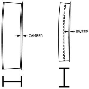
Positions for Measuring Camber and Sweep of W and HP Shapes
| Permitted Variation in Straightness, in. | |
|---|---|
| Camber and sweep | 1/8 × (number of feet of total length/10)A |
| When certain sectionsB with a flange width approximately equal to depth are specified in the order for use as columns: | |
| Lengths of 45 ft and under | 1/8 × (number of feet of total length/10) but not over 3/8 |
| Lengths over 45 ft | 3/8 + [1/8 × (number of feet of total length − 45)/10] |
ASections with a flange width less than 6 in., permitted variation for sweep, in. = 1/8 × (number of feet of total length/5).
BApplies only to:
8-in. deep sections 31 lb/ft and heavier,
10-in. deep sections 49 lb/ft and heavier,
12-in. deep sections 65 lb/ft and heavier,
14-in. deep sections 90 lb/ft and heavier,
16-in. deep sections 88 lb/ft and heavier, and
18-in. deep sections 135 lb/ft and heavier.
For other sections specified in the order for use as columns, the permitted variation is subject to negotiation with the manufacturer.
TABLE 25 Permitted Variations in Dimensions for Split Tees and Split Angles (L Shapes)A
| Specified Depth, in. | Permitted Variation Over or Under Specified Depth,B in. |
|---|---|
| To 6, excl (beams and channels) | 1/8 |
| 6 to 16, excl (beams and channels) | 3/16 |
| 16 to 20, excl (beams and channels) | 1/4 |
| 20 to 24, excl (beams) | 5/16 |
| 24 and over (beams) | 3/8 |
AThe permitted variations in length for split tees or angles are the same as those applicable to the section from which the tees or angles are split.
BThe above permitted variations in depth of tees or angles include the permitted variations in depth for the beams or channels before splitting. Permitted variations in dimensions and straightness, as set up for the beams or channels from which these tees or angles are cut, apply, except:
straightness = 1/8 in. × (length in feet/5)
TABLE 26 Permitted Variations in Sectional Dimensions for Square-Edge and Round-Edge Flat Bars
NOTE 1—Where “...” appears in this table, there is no requirement.
| Specified Widths, in. | Permitted Variations Over or Under Specified Thickness, for Thicknesses Given in Inches, in. | Permitted Variations From Specified Width, in. | |||||||
|---|---|---|---|---|---|---|---|---|---|
| 0.203 to 0.230, excl | 0.230 to 1/4, excl | 1/4 to 1/2, incl | Over 1/2 to 1, incl | Over 1 to 2, incl | Over 2 to 3, incl | Over 3 | Over | Under | |
| To 1, incl | 0.007 | 0.007 | 0.008 | 0.010 | ... | ... | ... | 1/64 | 1/64 |
| Over 1 to 2, incl | 0.007 | 0.007 | 0.012 | 0.015 | 1/32 | ... | ... | 1/32 | 1/32 |
| Over 2 to 4, incl | 0.008 | 0.008 | 0.015 | 0.020 | 1/32 | 3/64 | 3/64 | 1/16 | 1/32 |
| Over 4 to 6, incl | 0.009 | 0.009 | 0.015 | 0.020 | 1/32 | 3/64 | 3/64 | 3/32 | 1/16 |
| Over 6 to 8, incl | A | 0.015 | 0.016 | 0.025 | 1/32 | 3/64 | 1/16 | 1/8 B | 3/32 B |
AFlats over 6 to 8 in., incl, in width are not available as hot-rolled carbon steel bars in thickness under 0.230 in.
BFor flats over 6 to 8 in., in width, and to 3 in. incl in thickness.
TABLE 27 Permitted Variations in Sectional Dimensions for Round and Square Bars and Round-Cornered Squares
| Specified Size, in. | Permitted Variations from Specified Size, in. | Permitted Out-of-Round or Out-of-Square, in.A | |
|---|---|---|---|
| Over | Under | ||
| To 5/16 | 0.005 | 0.005 | 0.008 |
| Over 5/16 to 7/16, incl | 0.006 | 0.006 | 0.009 |
| Over 7/16 to 5/8, incl | 0.007 | 0.007 | 0.010 |
| Over 5/8 to 7/8, incl | 0.008 | 0.008 | 0.012 |
| Over 7/8 to 1, incl | 0.009 | 0.009 | 0.013 |
| Over 1 to 1 1/8, incl | 0.010 | 0.010 | 0.015 |
| Over 1 1/8 to 1 1/4, incl | 0.011 | 0.011 | 0.016 |
| Over 1 1/4 to 1 3/8, incl | 0.012 | 0.012 | 0.018 |
| Over 1 3/8 to 1 1/2, incl | 0.014 | 0.014 | 0.021 |
| Over 1 1/2 to 2, incl | 1/64 | 1/64 | 0.023 |
| Over 2 to 2 1/2, incl | 1/32 | 0 | 0.023 |
| Over 2 1/2 to 3 1/2, incl | 3/64 | 0 | 0.035 |
| Over 3 1/2 to 4 1/2, incl | 1/16 | 0 | 0.046 |
| Over 4 1/2 to 5 1/2, incl | 5/64 | 0 | 0.058 |
| Over 5 1/2 to 6 1/2, incl | 1/8 | 0 | 0.070 |
| Over 6 1/2 to 8 1/4, incl | 5/32 | 0 | 0.085 |
| Over 8 1/4 to 9 1/2, incl | 3/16 | 0 | 0.100 |
| Over 9 1/2 to 10, incl | 1/4 | 0 | 0.120 |
AOut-of-round is the difference between the maximum and minimum diameters of the bar, measured at the same transverse cross section. Out-of-square section is the difference in perpendicular distance between opposite faces, measured at the same transverse cross section.
TABLE 28 Permitted Variations in Sectional Dimensions for Hexagons
| Specified Sizes Between Opposite Sides, in. | Permitted Variations from Specified Size, in. | Permitted Out-of-Hexagon Section, Three Measurements, in.A | |
|---|---|---|---|
| Over | Under | ||
| 1/2 and under | 0.007 | 0.007 | 0.011 |
| Over 1/2 to 1, incl | 0.010 | 0.010 | 0.015 |
| Over 1 to 1 1/2, incl | 0.021 | 0.013 | 0.025 |
| Over 1 1/2 to 2, incl | 1/32 | 1/64 | 1/32 |
| Over 2 to 2 1/2, incl | 3/64 | 1/64 | 3/64 |
| Over 2 1/2 to 3 1/2, incl | 1/16 | 1/64 | 1/16 |
AOut-of-hexagon section is the greatest difference in distance between any two opposite faces measured at the same transverse cross section.
TABLE 29 Permitted Variations in Straightness for Bars
| Permitted Variations in Straightness, in.A |
|---|
| 1/4 in any 5 ft and 1/4 × (number of feet of total length/5) |
APermitted variations in straightness do not apply to hot-rolled bars if any subsequent heating operation has been performed.
TABLE 30 Permitted Variations in Length for Hot-Cut Steel BarsA
NOTE 1—Where “...” appears in this table, there is no requirement.
| Specified Sizes of Rounds, Squares, and Hexagons, in. | Specified Sizes of Flats, in. | Permitted Variations Over Specified Length Given in Feet, in. (No Variation Under) | |||||
|---|---|---|---|---|---|---|---|
| Thickness | Width | 5 to 10, excl | 10 to 20, excl | 20 to 30, excl | 30 to 40, excl | 40 to 60, incl | |
| To 1, incl | To 1, incl | To 3, incl | 1/2 | 3/4 | 1 1/4 | 1 3/4 | 2 1/4 |
| Over 1 to 2, incl | Over 1 | To 3, incl | 5/8 | 1 | 1 1/2 | 2 | 2 1/2 |
| Over 1 to 2, incl | To 1, incl | Over 3 to 6, incl | 5/8 | 1 | 1 1/2 | 2 | 2 1/2 |
| Over 2 to 5, incl | Over 1 | Over 3 to 6, incl | 1 | 1 1/2 | 1 3/4 | 2 1/4 | 2 3/4 |
| Over 5 to 10, incl | ... | ... | 2 | 2 1/2 | 2 3/4 | 3 | 3 1/4 |
| ... | 0.230 to 1, incl | Over 6 to 8, incl | 3/4 | 1 1/4 | 1 3/4 | 3 1/2 | 4 |
| ... | Over 1 to 3, incl | Over 6 to 8, incl | 1 1/4 | 1 3/4 | 2 | 3 1/2 | 4 |
| Hot Sawing | |||||||
| 2 to 5, inclB | 1 and over | 3 and over | B | 1 1/2 | 1 3/4 | 2 1/4 | 2 3/4 |
| Over 5 to 10, incl | ... | ... | B | 2 1/2 | 2 3/4 | 3 | 3 1/4 |
AFor flats over 6 to 8 in., incl, in width and over 3 in. in thickness, consult the manufacturer for permitted variations in length.
BSmaller sizes and shorter lengths are not commonly hot sawed.
TABLE 31 Permitted Variations in Length for Bars Recut Both Ends After StraighteningA,B
| Sizes of Rounds, Squares, Hexagons, Width of Flats and Maximum Dimension of Other Sections, in. | Permitted Variations from Specified Lengths Given in Feet, in. | |||
|---|---|---|---|---|
| To 12, incl | Over 12 | |||
| Over | Under | Over | Under | |
| To 3, incl | 3/16 | 1/16 | 1/4 | 1/16 |
| Over 3 to 6, incl | 1/4 | 1/16 | 3/8 | 1/16 |
| Over 6 to 8, incl | 3/8 | 1/16 | 1/2 | 1/16 |
| Rounds over 8 to 10, incl | 1/2 | 1/16 | 5/8 | 1/16 |
AFor flats over 6 to 8 in., incl, in width, and over 3 in. in thickness, consult the manufacturer or processor for permitted variations in length.
BPermitted variations are sometimes required all over or all under the specified length, in which case the sum of the two permitted variations applies.
SUPPLEMENTARY REQUIREMENTS
The following standardized supplementary requirements are for use when desired by the purchaser. Those that are considered suitable for use with each material specification are listed in the specification. Other tests may be performed by agreement between the supplier and the purchaser. These additional requirements shall apply only when specified in the order, in which event the specified tests shall be made by the manufacturer or processor before shipment of the material.
S1. Vacuum Treatment
S1.1 The steel shall be made by a process that includes vacuum degassing while molten. Unless otherwise agreed upon with the purchaser, it is the responsibility of the manufacturer to select suitable process procedures.
S2. Product Analysis
S2.1 Product analyses shall be made for those elements specified or restricted by the applicable product specification for the applicable grade, class, and type. Specimens for analysis shall be taken adjacent to or from the tension test specimen, or from a sample taken from the same relative location as that from which the tension test specimen was taken.
S3. Simulated Post-Weld Heat Treatment of Mechanical Test Coupons
S3.1 Prior to testing, the test specimens representing the structural product for acceptance purposes for mechanical properties shall be thermally treated to simulate a post-weld heat treatment below the critical temperature (Ac₃), using the heat treatment parameters (such as temperature range, time, and cooling rates) specified in the order. The test results for such heat-treated test specimens shall meet the applicable product specification requirements.
S4. Additional Tension Test
S4.1 Plate—One tension test shall be made from each unit plate rolled from a slab or directly from an ingot, except that for quenched and tempered plates, a test shall be taken from each unit plate heat treated. The results obtained shall be reported on the mill test reports when such tests are required by the order.
S5. Charpy V-Notch Impact Test
S5.1 Charpy V-notch impact tests shall be conducted in accordance with Specification A673/A673M.
S5.2 The frequency of testing, the test temperature to be used, and the absorbed energy requirements shall be as specified on the order.
S6. Drop-Weight Test (for Material 0.625 in. [16 mm] and Over in Thickness)
S6.1 Drop-weight tests shall be made in accordance with Test Method E208. The specimens shall represent the material in the final condition of heat treatment. Agreement shall be reached between the purchaser and the manufacturer or processor as to the number of pieces to be tested and whether a maximum nil-ductility transition (NDT) temperature is mandatory or if the test results are for information only.
S8. Ultrasonic Examination
S8.1 The material shall be ultrasonically examined in accordance with the requirements specified on the order.
S15. Reduction of Area Measurement
S15.1 The reduction of area, as determined on the 0.500-in. [12.5-mm] diameter round tension test specimen in accordance with Test Methods and Definitions A370, shall not be less than 40 %.
S18. Maximum Tensile Strength
S18.1 Steel having a specified minimum tensile strength of not more than 70 ksi [485 MPa] shall not exceed the minimum specified tensile strength by more than 30 ksi [205 MPa].
S18.2 Steel having a minimum specified tensile strength of 70 ksi [485 MPa] or higher shall not exceed the minimum specified tensile strength by more than 25 ksi [170 MPa].
S23. Copper-Bearing Steel (for improved atmospheric-corrosion-resistance)
S23.1 The copper content shall be a minimum of 0.20 % on heat analysis, 0.18 on product analysis.
S26. Subdivided Material—Marking of Individual Pieces
S26.1 Subdivided pieces shall be individually identified by marking, stenciling, or die stamping the applicable product specification designation (year-date not required), grade, heat number, and the heat treatment identification, if applicable, along with the trademark, brand, or name of the organization that subdivided the structural product. As an alternative, individual subdivided pieces shall be identified by a code traceable to the original required identification, provided that the trademark, name, or brand of the organization that subdivided the structural product is also placed on the structural product and the original required placification, cross-referenced on the code, is furnished with the structural product.
S27. Restrictive Plate Flatness
S27.1 As-rolled or normalized carbon steel plates ordered to restrictive flatness shall conform to the permitted variations from a flat surface given in Table S27.1 or Table S27.2, whichever is applicable.
S27.2 As-rolled or normalized high-strength low-alloy steel plates ordered to restrictive flatness shall conform to the permitted variations from a flat surface given in Table S27.3 or Table S27.4, whichever is applicable.
TABLE S27.1 Permitted Variations From a Flat Surface for As-Rolled or Normalized Carbon Steel Plates Ordered to Half-Standard Flatness
NOTE 1—Permitted Variation From a Flat Surface Along the Length—The longer dimension specified is considered the length, and the permitted variation from a flat surface along the length shall not exceed the tabular amount for the specified width in plates up to 12 ft in length, or in any 12 ft of longer plates.
NOTE 2—Permitted Variation From a Flat Surface Across the Width—The permitted variation from a flat surface across the width shall not exceed the tabular amount for the specified width.
NOTE 3—When the longer dimension is under 36 in., the permitted variation from a flat surface shall not exceed ¼ in. in each direction. When the longer dimension is from 36 to 72 in., incl, the permitted variation from a flat surface shall not exceed 75 % of the tabular amount for the specified width, but in no case less than ¼ in.
NOTE 4—The permitted variations given in this table apply to plates that have a minimum specified tensile strength not over 60 ksi or comparable chemistry or hardness. For plates specified to a higher minimum tensile strength or compatible chemistry or hardness, the permitted variations are 1½ times the amounts in this table.
NOTE 5—This table and these notes cover the permitted variations from a flat surface for circular and sketch plates, based upon the maximum dimensions of such plates.
NOTE 6—Permitted variations in waviness do not apply.
NOTE 7—Plates must be in a horizontal position on a flat surface when flatness is measured.
| Specified Thickness, in. | Specified Weights, lb/ft² | Permitted Variations From a Flat Surface for Specified Widths Given in Inches, in. | |||||
|---|---|---|---|---|---|---|---|
| 48 to 60, excl | 60 to 72, excl | 72 to 84, excl | 84 to 96, excl | 96 to 108, excl | 108 to 120, incl | ||
| To ¼, excl | To 10.2, excl | 15/32 | ⅝ | 11/16 | ¾ | 13/16 | 7/8 |
| ¼ to ⅜, excl | 10.2 to 15.3, excl | ⅜ | 15/32 | 9/16 | ⅝ | 11/16 | ¾ |
| ⅜ to ½, excl | 15.3 to 20.4, excl | 5/16 | 5/16 | ⅜ | 7/16 | ½ | 9/16 |
| ½ to ¾, excl | 20.4 to 30.6, excl | 9/32 | 5/16 | 5/16 | ⅜ | ½ | ½ |
| ¾ to 1, excl | 30.6 to 40.8, excl | 9/32 | 5/16 | 5/16 | 5/16 | ⅜ | 7/16 |
| 1 to 2, incl | 40.8 to 51.7, incl | ¼ | 9/32 | 9/32 | 5/16 | 5/16 | 5/16 |
TABLE S27.2 Permitted Variations From a Flat Surface for As-Rolled or Normalized Carbon Steel Plates Ordered to Half-Standard Flatness
NOTE 1—Permitted Variation From a Flat Surface Along the Length—The longer dimension specified is considered the length, and the permitted variation from a flat surface along the length shall not exceed the tabular amount for the specified width in plates up to 3700 mm in length, or in any 3700 mm of longer plates.
NOTE 2—Permitted Variation From a Flat Surface Across the Width—The permitted variation from a flat surface across the width shall not exceed the tabular amount for the specified width.
NOTE 3—When the longer dimension is under 900 mm, the permitted variation from a flat surface shall not exceed 6 mm in each direction. When the longer dimension is from 900 to 1800 mm, incl., the permitted flatness variation should not exceed 75 % of the tabular amount for the specified width but in no case less than 6 mm.
NOTE 4—The permitted variations given in this table apply to plates that have a minimum specified tensile strength not over 415 MPa or comparable chemistry or hardness. For plates specified to a higher minimum tensile strength or compatible chemistry or hardness, the permitted variations are 1½ times the amounts in this table.
NOTE 5—This table and these notes cover the permitted variations from a flat surface for circular and sketch plates, based upon the maximum dimensions of such plates.
NOTE 6—Permitted variations in waviness do not apply.
NOTE 7—Plates must be in a horizontal position on a flat surface when flatness is measured.
| Specified Thickness, mm | Specified Weights, kg/m² | Permitted Variations From a Flat Surface for Specified Widths Given in Millimetres, mm | |||||
|---|---|---|---|---|---|---|---|
| 1200 to 1500, excl | 1500 to 1800, excl | 1800 to 2100, excl | 2100 to 2400, excl | 2400 to 2700, excl | 2700 to 3000, incl | ||
| To 6, excl | To 47.1 excl | 12 | 16 | 17 | 19 | 20 | 22 |
| 6 to 10, excl | 47.1 to 78.5, excl. | 9 | 12 | 14 | 16 | 17 | 19 |
| 10 to 12, excl | 78.5 to 94.2, excl | 8 | 8 | 9 | 11 | 12 | 14 |
| 12 to 20, excl | 94.2 to 157.0, excl | 7 | 8 | 8 | 9 | 12 | 12 |
| 20 to 25, excl | 157.0 to 196.2, excl | 7 | 8 | 8 | 8 | 9 | 11 |
| 25 to 50, incl | 196.2 to 392.5, incl | 6 | 7 | 7 | 8 | 8 | 8 |
TABLE S27.3 Permitted Variations From a Flat Surface for As-Rolled or Normalized High-Strength Low-Alloy Steel Plates Ordered to Half-Standard Flatness
NOTE 1—Permitted Variation From a Flat Surface Along the Length—The longer dimension specified is considered the length, and the permitted variation from a flat surface along the length shall not exceed the tabular amount for the specified width in plates up to 12 ft in length, or in any 12 ft of longer plates.
NOTE 2—Permitted Variation From a Flat Surface Across the Width—The permitted variation from a flat surface across the width shall not exceed the tabular amount for the specified width.
NOTE 3—When the longer dimension is under 36 in., the permitted variation from a flat surface shall not exceed ⅜ in. in each direction. When the larger dimension is from 36 to 72 in., incl, the permitted variation from a flat surface shall not exceed 75 % of the tabular amount for the specified width, but in no case less than ⅜ in.
NOTE 4—This table and these notes cover the permitted variations from a flat surface for circular and sketch plates, based upon the maximum dimensions of those plates.
NOTE 5—Permitted variations in waviness do not apply.
NOTE 6—Plates must be in a horizontal position on a flat surface when flatness is measured.
| Specified Thickness, in. | Specified Weights, lb/ft² | Permitted Variations From a Flat Surface for Specified Widths Given in Inches, in. | |||||
|---|---|---|---|---|---|---|---|
| 48 to 60, excl | 60 to 72, excl | 72 to 84, excl | 84 to 96, excl | 96 to 108, excl | 108 to 120, incl | ||
| To ¼, excl | To 10.2 excl | 11/16 | 15/16 | 1 | 1 ⅛ | 1-3/16 | 1-5/16 |
| ¼ to ⅜, excl | 10.2 to 15.3, excl | 9/16 | 11/16 | 7/8 | 15/16 | 1 | 1 ⅛ |
| ⅜ to ½, excl | 15.3 to 20.4, excl | 15/32 | 15/32 | 9/16 | 21/32 | ¾ | 13/16 |
| ½ to ¾, excl | 20.4 to 30.6, excl | 13/32 | 7/16 | ½ | 9/16 | ⅝ | 11/16 |
| ¾ to 1, excl | 30.6 to 40.8, excl | 7/16 | 7/16 | 15/32 | ½ | 9/16 | 21/32 |
| 1 to 2, incl | 40.8 to 51.7, incl | ⅜ | 13/32 | 7/16 | 15/32 | ½ | ½ |
TABLE S27.4 Permitted Variations From a Flat Surface for As-Rolled or Normalized High-Strength Low-Alloy Steel Plates Ordered to Half-Standard Flatness
NOTE 1—Permitted Variation From a Flat Surface Along the Length—The longer dimension specified is considered the length, and the permitted variation from a flat surface along the length shall not exceed the tabular amount for the specified width in plates up to 3700 mm in length, or in any 3700 mm of longer plates.
NOTE 2—Permitted Variation From a Flat Surface Across the Width—The permitted variation from a flat surface across the width shall not exceed the tabular amount for the specified width.
NOTE 3—When the longer dimension is under 900 mm, the permitted variation from a flat surface shall not exceed 10 mm in each direction. When the larger dimension is from 900 to 1800 mm, incl., the permitted variation from a flat surface shall not exceed 75 % of the tabular amount for the specified width but in no case less than 10 mm.
NOTE 4—This table and these notes cover the permitted variations from a flat surface for circular and sketch plates, based upon the maximum dimensions of such plates.
NOTE 5—Permitted variations in waviness do not apply.
NOTE 6—Plates must be in a horizontal position on a flat surface when flatness is measured.
| Specified Thickness, mm | Specified Weights, kg/m² | Permitted Variations From a Flat Surface for Specified Widths Given in Millimetres, mm | |||||
|---|---|---|---|---|---|---|---|
| 1200 to 1500, excl | 1500 to 1800, excl | 1800 to 2100, excl | 2100 to 2400, excl | 2400 to 2700, excl | 2700 to 3000, incl | ||
| To 6, excl | To 47.1 excl | 17 | 24 | 25 | 28 | 30 | 33 |
| 6 to 10, excl | 47.1 to 78.5, excl | 14 | 17 | 22 | 24 | 25 | 28 |
| 10 to 12, excl | 78.5 to 94.2, excl | 12 | 12 | 14 | 16 | 19 | 20 |
| 12 to 20, excl | 94.2 to 157.0, excl | 11 | 11 | 12 | 14 | 16 | 17 |
| 20 to 25, excl | 157.0 to 196.2, excl | 11 | 11 | 12 | 12 | 14 | 16 |
| 25 to 50, incl | 196.2 to 392.5, incl | 9 | 10 | 11 | 12 | 12 | 12 |
S28. Fine Grain Practice
S28.1 The steel shall be made to fine grain practice.
S29. Fine Austenitic Grain Size
S29.1 The requirements for fine austenitic grain size (see 8.1 and 8.3) shall be met.
S30. Charpy V-Notch Impact Test for Structural Shapes: Alternate Core Location
S30.1 For shapes with a flange thickness equal to or greater than 1½ in. [38.1 mm] that are specified in the purchase order to be tested in accordance with this supplementary requirement, Charpy V-notch impact tests shall be conducted in accordance with Specification A673/A673M, using specimens taken from the alternate core location. Unless otherwise specified in the purchase order, the minimum average absorbed energy for each test shall be 20 ft·lbf [27 J] and the test temperature shall be 70°F [21°C].
S30.2 The frequency of testing shall be Frequency (H), except that, for rolled shapes produced from ingots, the frequency shall be Frequency (P) and the specimens shall be taken from a location representing the top of an ingot or part of an ingot used to produce the product represented by such specimens.
S31. Maximum Carbon Equivalent for Weldability
S31.1 Plates and shapes shall be supplied with a specific maximum carbon equivalent value as specified by the purchaser. This value shall be based upon heat analysis. The required chemical analysis as well as the carbon equivalent shall be reported.
S31.2 The carbon equivalent shall be calculated using the following formula:
CE = C + Mn/6 + (Cr+Mo+V)/5 + (Ni+Cu)/15
S31.3 For additional information on the weldability of steel, see Appendix X3.
S32. Single Heat Bundles
S32.1 Bundles containing shapes or bars shall be from a single heat of steel.
ANNEXES
(Mandatory Information)
A1. PERMITTED VARIATIONS IN DIMENSIONS AND MASS IN SI UNITS
A1.1 Tables A1.1-A1.31 inclusive contain permitted variations in dimensions and mass stated in SI Units.
TABLE A1.1 Permitted Variations in Thickness for Rectangular Carbon, High-Strength Low Alloy, and Alloy Steel Plates, 300 mm and Under in Thickness When Ordered to Thickness
Note 1—Permitted variation under specified thickness, 0.3 mm. When so ordered, these permitted variations may be taken all over, in which case the sum of these permitted variations applies.
Note 2—Thickness to be measured 10 to 20 mm from the longitudinal edge.
Note 3—For specified thicknesses not listed in this table, the permitted variations in thickness shall be as given for the next higher value of specified thickness that is listed in this table.
Note 4—For thickness measured at any location other than that specified in Note 2, the permitted variations over specified thickness shall be 1-3/4 times the amounts in this table, rounded to the nearest 0.1 mm.
Note 5—Where “....” appears in this table, there is no requirement.
| Specified Thickness, mm | Permitted Variations Over Specified Thickness for Widths Given in Millimetres, mm | ||||||||||
|---|---|---|---|---|---|---|---|---|---|---|---|
| 1200 and Under | Over 1200 to 1500, excl | 1500 to 1800, excl | Over 1800 to 2100, excl | 2100 to 2400, excl | 2400 to 2700, excl | 2700 to 3000, excl | 3000 to 3300, excl | 3300 to 3600, excl | 3600 to 4200, excl | 4200 and Over | |
| 5.0 | 0.8 | 0.8 | 0.8 | 0.8 | 0.8 | 0.8 | 0.8 | 0.9 | 1.0 | .... | .... |
| 5.5 | 0.8 | 0.8 | 0.8 | 0.8 | 0.8 | 0.8 | 0.8 | 0.9 | 1.0 | .... | .... |
| 6.0 | 0.8 | 0.8 | 0.8 | 0.8 | 0.8 | 0.8 | 0.8 | 1.0 | 1.1 | .... | .... |
| 7.0 | 0.8 | 0.8 | 0.8 | 0.8 | 0.8 | 0.8 | 0.9 | 1.0 | 1.2 | 1.4 | .... |
| 8.0 | 0.8 | 0.8 | 0.8 | 0.8 | 0.8 | 0.8 | 0.9 | 1.0 | 1.2 | 1.4 | .... |
| 9.0 | 0.8 | 0.8 | 0.8 | 0.8 | 0.8 | 0.8 | 1.0 | 1.0 | 1.3 | 1.5 | .... |
| 10.0 | 0.8 | 0.8 | 0.8 | 0.8 | 0.8 | 0.8 | 1.0 | 1.0 | 1.3 | 1.5 | 1.7 |
| 11.0 | 0.8 | 0.8 | 0.8 | 0.8 | 0.8 | 0.8 | 1.0 | 1.0 | 1.3 | 1.5 | 1.7 |
| 12.0 | 0.8 | 0.8 | 0.8 | 0.8 | 0.8 | 0.9 | 1.0 | 1.0 | 1.3 | 1.5 | 1.8 |
| 14.0 | 0.8 | 0.8 | 0.8 | 0.8 | 0.9 | 0.9 | 1.0 | 1.1 | 1.3 | 1.5 | 1.8 |
| 16.0 | 0.8 | 0.8 | 0.8 | 0.8 | 0.9 | 0.9 | 1.0 | 1.1 | 1.3 | 1.5 | 1.8 |
| 18.0 | 0.8 | 0.8 | 0.8 | 0.8 | 0.9 | 1.0 | 1.1 | 1.2 | 1.4 | 1.6 | 2.0 |
| 20.0 | 0.8 | 0.8 | 0.8 | 0.8 | 0.9 | 1.0 | 1.2 | 1.2 | 1.4 | 1.6 | 2.0 |
| 22.0 | 0.8 | 0.9 | 0.9 | 0.9 | 1.0 | 1.1 | 1.3 | 1.3 | 1.5 | 1.8 | 2.0 |
| 25.0 | 0.9 | 0.9 | 1.0 | 1.0 | 1.0 | 1.2 | 1.3 | 1.5 | 1.5 | 1.8 | 2.2 |
| 28.0 | 1.0 | 1.0 | 1.1 | 1.1 | 1.1 | 1.3 | 1.4 | 1.8 | 1.8 | 2.0 | 2.2 |
| 30.0 | 1.1 | 1.1 | 1.2 | 1.2 | 1.2 | 1.4 | 1.5 | 1.8 | 1.8 | 2.1 | 2.4 |
| 32.0 | 1.2 | 1.2 | 1.3 | 1.3 | 1.3 | 1.5 | 1.6 | 2.0 | 2.0 | 2.3 | 2.6 |
| 35.0 | 1.3 | 1.3 | 1.4 | 1.4 | 1.4 | 1.6 | 1.7 | 2.3 | 2.3 | 2.5 | 2.8 |
| 38.0 | 1.4 | 1.4 | 1.5 | 1.5 | 1.5 | 1.7 | 1.8 | 2.3 | 2.3 | 2.7 | 3.0 |
| 40.0 | 1.5 | 1.5 | 1.6 | 1.6 | 1.6 | 1.8 | 2.0 | 2.5 | 2.5 | 2.8 | 3.3 |
| 45.0 | 1.6 | 1.6 | 1.7 | 1.8 | 1.8 | 2.0 | 2.3 | 2.8 | 2.8 | 3.0 | 3.5 |
| 50.0 | 1.8 | 1.8 | 1.8 | 2.0 | 2.0 | 2.3 | 2.5 | 3.0 | 3.0 | 3.3 | 3.8 |
| 55.0 | 2.0 | 2.0 | 2.0 | 2.2 | 2.2 | 2.5 | 2.8 | 3.3 | 3.3 | 3.5 | 3.8 |
| 60.0 | 2.3 | 2.3 | 2.3 | 2.4 | 2.4 | 2.8 | 3.0 | 3.4 | 3.4 | 3.8 | 4.0 |
| 70.0 | 2.5 | 2.5 | 2.5 | 2.6 | 2.6 | 3.0 | 3.3 | 3.5 | 3.6 | 4.0 | 4.0 |
| 80.0 | 2.8 | 2.8 | 2.8 | 2.8 | 2.8 | 3.3 | 3.5 | 3.5 | 3.6 | 4.0 | 4.0 |
| 90.0 | 3.0 | 3.0 | 3.0 | 3.0 | 3.0 | 3.5 | 3.5 | 3.5 | 3.6 | 4.0 | 4.4 |
| 100.0 | 3.3 | 3.3 | 3.3 | 3.3 | 3.5 | 3.8 | 3.8 | 3.8 | 3.8 | 4.4 | 4.4 |
| 110.0 | 3.5 | 3.5 | 3.5 | 3.5 | 3.5 | 3.8 | 3.8 | 3.8 | 3.8 | 4.4 | 4.4 |
| 120.0 | 3.8 | 3.8 | 3.8 | 3.8 | 3.8 | 3.8 | 3.8 | 3.8 | 3.8 | 4.8 | 4.8 |
| 130.0 | 4.0 | 4.0 | 4.0 | 4.0 | 4.0 | 4.0 | 4.0 | 4.0 | 4.0 | 5.2 | 5.2 |
| 140.0 | 4.3 | 4.3 | 4.3 | 4.3 | 4.3 | 4.3 | 4.3 | 4.3 | 4.3 | 5.6 | 5.6 |
| 150.0 | 4.5 | 4.5 | 4.5 | 4.5 | 4.5 | 4.5 | 4.5 | 4.5 | 4.5 | 5.6 | 5.6 |
| 160.0 | 4.8 | 4.8 | 4.8 | 4.8 | 4.8 | 4.8 | 4.8 | 4.8 | 4.8 | 5.6 | 5.6 |
| 180.0 | 5.4 | 5.4 | 5.4 | 5.4 | 5.4 | 5.4 | 5.4 | 5.4 | 5.4 | 6.3 | 6.3 |
| 200.0 | 5.8 | 5.8 | 6.0 | 6.0 | 6.0 | 6.0 | 6.0 | 6.0 | 6.0 | 7.0 | 7.0 |
| 250.0 | 7.5 | 7.5 | 7.5 | 7.5 | 7.5 | 7.5 | 7.5 | 7.5 | 7.5 | 7.5 | 8.8 |
| 300.0 | 7.5 | 7.5 | 9.0 | 9.0 | 9.0 | 9.0 | 9.0 | 9.0 | 9.0 | 9.0 | 9.0 |
TABLE A1.2 Permitted Variations in Mass for Rectangular Sheared Plates and Universal Mill Plates 2983 kg/m² and Under When Ordered to Mass
NOTE 1—Permitted variations in excess mass for lots of circular and sketch plates shall be 1¼ times the amounts in this table.
NOTE 2—Permitted variations in excess mass for single plates shall be 1⅓ times the amounts in this table.
NOTE 3—Permitted variations in excess mass for single circular and sketch plates shall be 1⅔ times the amounts in this table.
NOTE 4—The adopted standard density for rolled steel is 7850 kg/m³.
NOTE 5—Where “...” appears in this table, there is no requirement.
| Specified Mass, kg/m² | Permitted Variations in Average Mass of LotsA for Widths Given in Millimetres, Expressed in Percentage of the Specified Masses per Square Metre | |||||||||||||||||||||
|---|---|---|---|---|---|---|---|---|---|---|---|---|---|---|---|---|---|---|---|---|---|---|
| 1200 and Under | Over 1200 to 1500, excl | 1500 to 1800, excl | 1800 to 2100, excl | 2100 to 2400, excl | 2400 to 2700, excl | 2700 to 3000, excl | 3000 to 3300, excl | 3300 to 3600, excl | 3600 to 4200, excl | 4200 and Over | ||||||||||||
| Over | Under | Over | Under | Over | Under | Over | Under | Over | Under | Over | Under | Over | Under | Over | Under | Over | Under | Over | Under | Over | Under | |
| To 51.02, excl | 4.0 | 3.0 | 4.5 | 3.0 | 5.0 | 3.0 | 5.5 | 3.0 | 6.0 | 3.0 | 7.5 | 3.0 | 9.0 | 3.0 | .... | .... | .... | .... | .... | .... | .... | .... |
| 51.02 to 62.80, excl | 4.0 | 3.0 | 4.5 | 3.0 | 5.0 | 3.0 | 5.5 | 3.0 | 6.0 | 3.0 | 6.5 | 3.0 | 7.0 | 3.0 | 8.0 | 3.0 | 9.0 | 3.0 | .... | .... | .... | .... |
| 62.80 to 74.58, excl | 4.0 | 3.0 | 4.0 | 3.0 | 4.5 | 3.0 | 5.0 | 3.0 | 5.5 | 3.0 | 5.5 | 3.0 | 6.0 | 3.0 | 7.5 | 3.0 | 8.0 | 3.0 | 11 | 3.0 | .... | .... |
| 74.58 to 86.35, excl | 3.5 | 3.0 | 3.5 | 3.0 | 4.0 | 3.0 | 4.5 | 3.0 | 5.0 | 3.0 | 5.0 | 3.0 | 5.5 | 3.0 | 6.0 | 3.0 | 7.0 | 3.0 | 9.0 | 3.0 | 10 | 3.0 |
| 86.35 to 102.0, excl | 3.5 | 2.5 | 3.5 | 2.5 | 3.5 | 3.0 | 4.0 | 3.0 | 4.5 | 3.0 | 4.5 | 3.0 | 5.0 | 3.0 | 5.5 | 3.0 | 6.0 | 3.0 | 8.0 | 3.0 | 9.0 | 3.0 |
| 102.0 to 125.6, excl | 3.5 | 2.5 | 3.5 | 2.5 | 3.5 | 3.0 | 3.5 | 3.0 | 4.0 | 3.0 | 4.0 | 3.0 | 4.5 | 3.0 | 5.0 | 3.0 | 5.5 | 3.0 | 7.0 | 3.0 | 8.0 | 3.0 |
| 125.6 to 149.2, excl | 3.0 | 2.5 | 3.5 | 2.5 | 3.5 | 2.5 | 3.5 | 3.0 | 3.5 | 3.0 | 3.5 | 3.0 | 4.0 | 3.0 | 4.5 | 3.0 | 5.0 | 3.0 | 6.5 | 3.0 | 7.0 | 3.0 |
| 149.2 to 196.2, excl | 3.0 | 2.0 | 3.0 | 2.0 | 3.0 | 2.0 | 3.0 | 2.0 | 3.5 | 2.0 | 3.5 | 2.5 | 3.5 | 2.5 | 4.0 | 3.0 | 4.5 | 3.0 | 6.0 | 3.0 | 6.5 | 3.0 |
| 196.2 to 392.5, excl | 2.5 | 2.0 | 3.0 | 2.0 | 3.0 | 2.0 | 3.0 | 2.0 | 3.5 | 2.0 | 3.5 | 2.0 | 3.5 | 2.5 | 3.5 | 3.0 | 4.0 | 3.0 | 5.5 | 3.0 | 6.0 | 3.0 |
| 392.5 to 588.8, excl | 2.5 | 2.0 | 3.0 | 2.0 | 3.0 | 2.0 | 3.0 | 2.0 | 3.5 | 2.0 | 3.5 | 2.0 | 3.5 | 2.5 | 3.5 | 3.0 | 3.5 | 3.0 | 4.0 | 3.0 | 4.5 | 3.0 |
| 588.8 to 785.0, excl | 2.5 | 1.5 | 2.5 | 1.5 | 2.5 | 1.5 | 2.5 | 1.5 | 2.5 | 2.0 | 2.5 | 2.0 | 2.5 | 2.0 | 2.5 | 2.0 | 2.5 | 2.0 | 3.0 | 2.0 | 3.5 | 2.0 |
| 785.0 to 1178, excl | 2.5 | 1.0 | 2.5 | 1.0 | 2.5 | 1.0 | 2.5 | 1.0 | 2.5 | 1.0 | 2.5 | 1.0 | 2.5 | 1.0 | 2.5 | 1.0 | 2.5 | 1.0 | 3.0 | 1.0 | 3.5 | 1.0 |
| 1178 to 1962, excl | 2.5 | 1.0 | 2.5 | 1.0 | 2.5 | 1.0 | 2.5 | 1.0 | 2.5 | 1.0 | 2.5 | 1.0 | 2.5 | 1.0 | 2.5 | 1.0 | 2.5 | 1.0 | 2.5 | 1.0 | 3.0 | 1.0 |
| 1962 to 2355, incl | 2.0 | 1.0 | 2.0 | 1.0 | 2.5 | 1.0 | 2.5 | 1.0 | 2.5 | 1.0 | 2.5 | 1.0 | 2.5 | 1.0 | 2.5 | 1.0 | 2.5 | 1.0 | 2.5 | 1.0 | 2.5 | 1.0 |
| 2355 to 2983, incl | 2.0 | 1.0 | 2.0 | 1.0 | 2.0 | 1.0 | 2.0 | 1.0 | 2.5 | 1.0 | 2.5 | 1.0 | 2.5 | 1.0 | 2.5 | 1.0 | 2.5 | 1.0 | 2.5 | 1.0 | 2.5 | 1.0 |
AThe term “lot” means all the plates of each tabular width and mass group represented in each shipment.
TABLE A1.3 Permitted Variations in Width and Length for Sheared Plates 40 mm and Under in Thickness; Length Only of Universal Mill Plates 65 mm and Under in Thickness
| Specified Dimensions, mm | Permitted Variations Over Specified Width and LengthA for Thicknesses Given in Millimetres and Equivalent Masses Given in Kilograms per Square Metre, mm | ||||||||
|---|---|---|---|---|---|---|---|---|---|
| To 10.50, excl To 78.50, excl |
10.50 to 16 excl78.50 to 125.6, excl |
16 to 25 125.6 to 196.2, excl |
25 to 50B 196.2 to 392.5, incl |
||||||
| Width | Length | Width | Length | Width | Length | Width | Length | Length | Width |
| To 3000, excl | To 1500, excl | 10 | 13 | 11 | 16 | 13 | 19 | 16 | 25 |
| 1500 to 2100, excl | 11 | 16 | 13 | 18 | 16 | 22 | 19 | 25 | |
| 2100 to 2700, excl | 13 | 19 | 16 | 22 | 19 | 25 | 25 | 29 | |
| 2700 and over | 16 | 22 | 19 | 25 | 22 | 29 | 29 | 32 | |
| 3000 to 6000, excl | To 1500, excl | 10 | 19 | 13 | 22 | 16 | 25 | 19 | 29 |
| 1500 to 2100, excl | 13 | 19 | 16 | 22 | 19 | 25 | 22 | 32 | |
| 2100 to 2700, excl | 14 | 22 | 18 | 24 | 21 | 29 | 25 | 35 | |
| 2700 and over | 16 | 25 | 19 | 29 | 22 | 32 | 29 | 35 | |
| 6000 to 9000, excl | To 1500, excl | 10 | 25 | 13 | 29 | 16 | 32 | 19 | 38 |
| 1500 to 2100, excl | 13 | 25 | 16 | 29 | 19 | 32 | 22 | 38 | |
| 2100 to 2700, excl | 14 | 25 | 18 | 32 | 22 | 35 | 25 | 38 | |
| 2700 and over | 18 | 29 | 22 | 32 | 25 | 35 | 32 | 44 | |
| 9000 to 12 000, excl | To 1500, excl | 11 | 29 | 13 | 32 | 16 | 35 | 19 | 41 |
| 1500 to 2100, excl | 13 | 32 | 16 | 35 | 19 | 38 | 22 | 41 | |
| 2100 to 2700, excl | 14 | 32 | 19 | 35 | 22 | 38 | 25 | 48 | |
| 2700 and over | 19 | 35 | 22 | 38 | 25 | 41 | 32 | 48 | |
| 12 000 to 15 000, excl | To 1500, excl | 11 | 32 | 13 | 38 | 16 | 41 | 19 | 48 |
| 1500 to 2100, excl | 13 | 35 | 16 | 38 | 19 | 41 | 22 | 48 | |
| 2100 to 2700, excl | 16 | 35 | 19 | 38 | 22 | 41 | 25 | 48 | |
| 2700 and over | 19 | 38 | 22 | 41 | 25 | 44 | 32 | 48 | |
| 15 000 to 18 000, excl | To 1500, excl | 13 | 44 | 16 | 48 | 19 | 48 | 22 | 57 |
| 1500 to 2100, excl | 16 | 44 | 19 | 48 | 22 | 48 | 25 | 57 | |
| 2100 to 2700, excl | 22 | 44 | 19 | 48 | 22 | 48 | 29 | 57 | |
| 2700 and over | 16 | 44 | 25 | 51 | 29 | 57 | 32 | 64 | |
| 18 000 and over | To 1500, excl | 14 | 51 | 19 | 54 | 22 | 57 | 25 | 70 |
| 1500 to 2100, excl | 19 | 51 | 22 | 54 | 25 | 57 | 29 | 70 | |
| 2100 to 2700, excl | 25 | 51 | 22 | 54 | 25 | 57 | 32 | 70 | |
| 2700 and over | 19 | 51 | 29 | 60 | 32 | 64 | 35 | 76 | |
APermitted variations under specified width and length, 6 mm. By agreement, these permitted variations may be taken all over, in which case the sum of the permitted variations applies.
BPermitted variations in length apply also to Universal Mill plates up to 300 mm in width for thicknesses over 50 to 65 mm, incl, except for alloy steel up to 50 mm thick.
TABLE A1.4 Permitted Variations in Width for Mill Edge Carbon and High Strength Low-Alloy Plates Produced on Strip Mills (Applies to Plates Produced from Coil and to Plates Produced from an As-Rolled Structural Product)
| Specified Width, mm | Permitted Variation Over Specified Width, mmA |
|---|---|
| To 360, excl | 11 |
| 360 to 430, excl | 13 |
| 430 to 480, excl | 14 |
| 480 to 530, excl | 16 |
| 530 to 610, excl | 17 |
| 610 to 660, excl | 21 |
| 660 to 710, excl | 24 |
| 710 to 890, excl | 29 |
| 890 to 1270, excl | 32 |
| 1270 to 1520, excl | 38 |
| 1520 to 1650, excl | 41 |
| 1650 to 1780, excl | 44 |
| 1780 to 2030, excl | 47 |
| 2030 and over | 51 |
ANo permitted variation under specified width.
TABLE A1.5 Permitted Variations in Rolled Width for Universal Mill Plates 380 mm and Under in Thickness
| Specified Width, mm | Permitted Variations Over Specified WidthA for Thickness Given in Millimetres or Equivalent Masses Given in Kilograms per Square Metre, mm | |||||
|---|---|---|---|---|---|---|
| To 10, excl | 10 to 16, excl | 16 to 25, incl | 25 to 50, incl | Over 50 to 250, incl | Over 250 to 400, incl | |
| To 78.50, excl | 78.50 to 125.6, excl | 125.6 to 196.2, excl | 196.2 to 392.5, incl | 392.5 to 1962, incl | 1962 to 3140, incl | |
| Over 200 to 500, excl | 3 | 3 | 5 | 6 | 10 | 13 |
| 500 to 900, excl | 5 | 6 | 8 | 10 | 11 | 14 |
| 900 and over | 8 | 10 | 11 | 13 | 14 | 16 |
APermitted variation under specified width, 3 mm.
TABLE A1.6 Permitted Variations in Diameter for Sheared Circular Plates 25 mm and Under in Thickness
| Specified Diameters, mm | Permitted Variations Over Specified Diameter for Thicknesses Given in Millimetres, mmA | ||
|---|---|---|---|
| To 10, excl | 10 to 16, excl | 16 to 25, incl | |
| To 800, excl | 6 | 10 | 13 |
| 800 to 2100, excl | 8 | 11 | 14 |
| 2100 to 2700, excl | 10 | 13 | 16 |
| 2700 to 3300, excl | 11 | 14 | 17 |
| 3300 and over | 13 | 16 | 19 |
ANo permitted variation under specified diameter.
TABLE A1.7 Permitted Variations in Diameter for Gas-Cut Circular Plates (Not Applicable to Alloy Steel)
| Specified Diameters, mm | Permitted Variation Over Specified Diameter for Thicknesses Given, mmA | |||||
|---|---|---|---|---|---|---|
| To 25, excl | 25 to 50, excl | 50 to 100, excl | 100 to 150, excl | 150 to 200, excl | 200 to 400, incl | |
| To 800, excl | 10 | 10 | 13 | 13 | 16 | 19 |
| 800 to 2100, excl | 10 | 13 | 13 | 16 | 19 | 22 |
| 2100 to 2700, excl | 13 | 14 | 16 | 19 | 22 | 25 |
| 2700 to 3300, excl | 13 | 14 | 17 | 22 | 25 | 29 |
| 3300 and over | 16 | 19 | 22 | 25 | 29 | 32 |
ANo permitted variations under specified diameter.
TABLE A1.8 Permitted Variations in Width and Length for Rectangular Plates When Gas Cutting is Specified or Required (Applies to Alloy Steel Specifications Only)
NOTE 1—Plates with universal rolled edges will be gas cut to length only.
NOTE 2—These permitted variations shall be taken all under or divided over and under, if so specified.
| Specified Thickness, mm | Permitted Variation Over Specified Width and Length, mm |
|---|---|
| To 50, excl | 19 |
| 50 to 100, excl | 25 |
| 100 to 150, excl | 29 |
| 150 to 200, excl | 33 |
| 200 to 400, excl | 38 |
TABLE A1.9 Permitted Variations in Width and Length for Rectangular Plates When Gas Cutting is Specified or Required (Not Applicable to Alloy Steel)
NOTE 1—Plates with universal rolled edges will be gas cut to length only.
| Specified Thickness, mm | Permitted Variation Over Specified Width and Length, mmA |
|---|---|
| To 50, excl | 13 |
| 50 to 100, excl | 16 |
| 100 to 150, excl | 19 |
| 150 to 200, excl | 22 |
| 200 to 400, incl | 25 |
AThese permitted variations shall be taken all under or divided over and under, if so specified.
TABLE A1.10 Permitted Variations in Diameter for Gas-Cut Circular Plates (Applies to Alloy Steel Specifications Only)
| Specified Diameter, mm | Permitted Variations Over Specified Diameter for Specified Thicknesses Given in Millimetres, mmA | |||||
|---|---|---|---|---|---|---|
| To 25, excl | 25 to 50, excl | 50 to 100, excl | 100 to 150, excl | 150 to 200, excl | 200 to 400, incl | |
| To 800, excl | 13 | 13 | 19 | 19 | 25 | 25 |
| 800 to 2100, excl | 13 | 16 | 22 | 25 | 29 | 32 |
| 2100 to 2700, excl | 16 | 19 | 25 | 29 | 32 | 35 |
| 2700 to 3300, incl | 22 | 25 | 29 | 32 | 35 | 38 |
ANo permitted variations under specified diameter.
TABLE A1.11 Permitted CamberA for Carbon Steel, High-Strength Low-Alloy Steel and Alloy Steel Universal Mill, High-Strength Low-Alloy Steel and Alloy Steel Sheared or Gas-Cut Rectangular Plates
| Specified Width, mm | Permitted Camber, mm |
|---|---|
| To 750, incl | Length in millimetres/300 |
| Over 750 to 1500 | Length in millimetres/250 |
ACamber as it relates to plates is the horizontal edge curvature in the length, measured over the entire length of the plate in the flat position.
TABLE A1.12 Permitted CamberA for Sheared Plates and Gas-Cut Rectangular Plates, All Thicknesses (Applies to Carbon Steel Only)
| Permitted camber, mm = length in millimetres/500 |
|---|
ACamber as it relates to plates is the horizontal edge curvature in the length, measured over the entire length of the plate in the flat position.
TABLE A1.13 Permitted Variations From a Flat Surface for Standard Flatness Carbon Steel Plates
NOTE 1—When the longer dimension is under 900 mm, the permitted variation from a flat surface shall not exceed 6 mm. When the longer dimension is from 900 to 1800 mm, incl, the permitted variation from a flat surface shall not exceed 75 % of the tabular amount for the specified width, but in no case less than 6 mm.
NOTE 2—These permitted variations apply to plates that have a specified minimum tensile strength of not more than 415 MPa or comparable chemical composition or hardness. The limits in this table are increased 50 % for plates that have a higher specified minimum tensile strength or comparable chemical composition or hardness.
NOTE 3—This table and these notes cover the permitted variations from a flat surface for circular and sketch plates, based upon the maximum dimensions of such plates.
NOTE 4—Where “....” appears in this table, there is no requirement.
NOTE 5—Plates must be in a horizontal position on a flat surface when flatness is measured.
| Specified Thickness, mm | Specified Mass, kg/m² | Permitted Variations From a Flat Surface for Specified Widths Given in Millimetres, mmA,B | ||||||||||
|---|---|---|---|---|---|---|---|---|---|---|---|---|
| To 900, excl | 900 to 1200, excl | 1200 to 1500, excl | 1500 to 1800, excl | 1800 to 2100, excl | 2100 to 2400, excl | 2400 to 2700, excl | 2700 to 3000, excl | 3000 to 3600, excl | 3600 to 4200, excl | 4200 and over | ||
| To 6, excl | To 47.1, excl | 14 | 19 | 24 | 32 | 35 | 38 | 41 | 44 | 48 | .... | .... |
| 6 to 10, excl | 47.1 to 78.5, excl | 13 | 16 | 19 | 24 | 29 | 32 | 35 | 38 | 41 | .... | .... |
| 10 to 12, excl | 78.5 to 94.2, excl | 13 | 14 | 16 | 16 | 19 | 22 | 25 | 29 | 32 | 48 | 54 |
| 12 to 20, excl | 94.2 to 157.0, excl | 11 | 13 | 14 | 16 | 16 | 19 | 25 | 25 | 29 | 38 | 51 |
| 20 to 25, excl | 157.0 to 196.2, excl | 11 | 13 | 14 | 16 | 16 | 16 | 19 | 22 | 25 | 35 | 44 |
| 25 to 50, excl | 196.2 to 392.5, excl | 10 | 13 | 13 | 14 | 14 | 16 | 16 | 16 | 18 | 29 | 38 |
| 50 to 100, excl | 392.5 to 785.0, excl | 8 | 10 | 11 | 13 | 13 | 13 | 13 | 14 | 16 | 22 | 29 |
| 100 to 150, excl | 785.0 to 1178, excl | 10 | 11 | 13 | 13 | 14 | 14 | 16 | 19 | 22 | 22 | 25 |
| 150 to 200, excl | 1178 to 1570, excl | 11 | 13 | 13 | 16 | 18 | 19 | 22 | 22 | 25 | 25 | 25 |
| 200 to 250, excl | 1570 to 1962, excl | 13 | 13 | 16 | 18 | 19 | 21 | 22 | 24 | 25 | 25 | 25 |
| 250 to 300, excl | 1962 to 2355, excl | 13 | 16 | 19 | 21 | 22 | 24 | 25 | 25 | 25 | 25 | 25 |
| 300 to 400, incl | 2355 to 3140, incl | 16 | 19 | 21 | 22 | 24 | 25 | 25 | 25 | 25 | 25 | .... |
APermitted Variation From a Flat Surface Along the Length—The longer dimension specified is considered the length, and the permitted variation from a flat surface along the length shall not exceed the tabular amount for the specified width for plates up to 4000 mm in length, or in any 4000 mm for longer plates.
BPermitted Variation From a Flat Surface Across the Width—The permitted variation from a flat surface across the width shall not exceed the tabular amount for the specified width.
TABLE A1.14 Permitted Variations From a Flat Surface for Standard Flatness High-Strength Low-Alloy Steel and Alloy Steel Plates, Hot Rolled or Thermally Treated
NOTE 1—When the longer dimension is under 900 mm, the permitted variation from a flat surface shall not exceed 10 mm. When the longer dimension is from 900 to 1800 mm, incl, the permitted variation from a flat surface shall not exceed 75 % of the tabular amount for the specified width.
NOTE 2—This table and these notes cover the permitted variations from a flat surface for circular and sketch plates, based upon the maximum dimensions of such plates.
NOTE 3—Where “....” appears in this table, there is no requirement.
NOTE 4—Plates must be in a horizontal position on a flat surface when flatness is measured.
| Specified Thickness, mm | Specified Mass, kg/m² | Permitted Variations from a Flat Surface for Specified Widths Given in Millimetres, mmA,B | ||||||||||
|---|---|---|---|---|---|---|---|---|---|---|---|---|
| To 900, excl | 900 to 1200, excl | 1200 to 1500, excl | 1500 to 1800, excl | 1800 to 2100, excl | 2100 to 2400, excl | 2400 to 2700, excl | 2700 to 3000, excl | 3000 to 3600, excl | 3600 to 4200, excl | 4200 and over | ||
| To 6, excl | To 47.1, excl | 21 | 29 | 35 | 48 | 51 | 57 | 60 | 67 | 70 | .... | .... |
| 6 to 10, excl | 47.1 to 78.5, excl | 19 | 24 | 29 | 35 | 44 | 48 | 51 | 57 | 60 | .... | .... |
| 10 to 12, excl | 78.5 to 94.2, excl | 19 | 22 | 24 | 24 | 29 | 33 | 38 | 41 | 48 | 70 | 79 |
| 12 to 20, excl | 94.2 to 157.0, excl | 16 | 19 | 22 | 22 | 25 | 29 | 32 | 35 | 41 | 57 | 76 |
| 20 to 25, excl | 157.0 to 196.2, excl | 16 | 19 | 22 | 22 | 24 | 25 | 29 | 33 | 38 | 51 | 67 |
| 25 to 50, excl | 196.2 to 392.5, excl | 14 | 16 | 19 | 21 | 22 | 24 | 25 | 25 | 25 | 41 | 57 |
| 50 to 100, excl | 392.5 to 785.0, excl | 13 | 14 | 18 | 19 | 19 | 19 | 19 | 22 | 25 | 32 | 41 |
| 100 to 150, excl | 785.0 to 1178, excl | 14 | 18 | 19 | 19 | 22 | 22 | 24 | 29 | 32 | 32 | 38 |
| 150 to 200, excl | 1178 to 1570, excl | 16 | 19 | 19 | 24 | 25 | 29 | 32 | 33 | 38 | 38 | 38 |
| 200 to 250, excl | 1570 to 1962, excl | 19 | 21 | 24 | 25 | 29 | 32 | 33 | 35 | 38 | 38 | 38 |
| 250 to 300, excl | 1962 to 2355, incl | 19 | 24 | 29 | 32 | 33 | 35 | 38 | 38 | 38 | 38 | 38 |
| 300 to 400, incl | 2355 to 3140, incl | 22 | 25 | 30 | 33 | 35 | 35 | 38 | 38 | 38 | 38 | 38 |
APermitted Variation From a Flat Surface Along the Length—The longer dimension specified is considered the length, and the permitted variation from a flat surface along the length shall not exceed the tabular amount for the specified width in plates up to 4000 mm in length, or in any 4000 mm for longer plates.
BPermitted Variation From a Flat Surface Across the Width—The permitted variation from a flat surface across the width shall not exceed the tabular amount for the specified width.
TABLE A1.15 Permitted Variations in Waviness for Standard Flatness Plates
NOTE 1—Waviness denotes the maximum deviation of the surface of the plate from a plane parallel to the surface of the point of measurement and contiguous to the surface of the place at each of the two adjacent wave peaks, when the plate is resting on a flat horizontal surface, as measured in an increment of less than 4000 mm of length. The permitted variation in waviness is a function of the permitted variation from a flat surface as obtained from Table A1.13 or Table A1.14, whichever is applicable.
NOTE 2—Plates must be in a horizontal position on a flat surface when waviness is measured.
| Permitted Variation from a Flat Surface (From Table A1.13 or Table A1.14), mm | Permitted Variations in Waviness, mm, When Number of Waves in 4000 mm is | ||||||
|---|---|---|---|---|---|---|---|
| 1 | 2 | 3 | 4 | 5 | 6 | 7 | |
| 8 | 8 | 6 | 5 | 3 | 3 | 2 | 2 |
| 10 | 10 | 8 | 5 | 5 | 3 | 2 | 2 |
| 11 | 11 | 8 | 6 | 5 | 3 | 3 | 2 |
| 13 | 13 | 10 | 8 | 5 | 5 | 3 | 2 |
| 14 | 14 | 11 | 8 | 6 | 5 | 3 | 2 |
| 16 | 16 | 13 | 10 | 6 | 5 | 3 | 2 |
| 17 | 17 | 13 | 10 | 8 | 5 | 5 | 2 |
| 19 | 19 | 14 | 11 | 8 | 6 | 5 | 2 |
| 21 | 21 | 16 | 11 | 8 | 6 | 5 | 2 |
| 22 | 22 | 17 | 13 | 10 | 6 | 5 | 2 |
| 24 | 24 | 17 | 13 | 10 | 8 | 6 | 5 |
| 25 | 25 | 19 | 14 | 11 | 8 | 6 | 5 |
| 29 | 29 | 22 | 16 | 13 | 10 | 6 | 5 |
| 32 | 32 | 24 | 17 | 13 | 10 | 8 | 6 |
| 35 | 35 | 27 | 19 | 14 | 11 | 8 | 6 |
| 38 | 38 | 29 | 22 | 16 | 13 | 10 | 6 |
| 41 | 41 | 32 | 24 | 17 | 13 | 10 | 8 |
| 44 | 44 | 33 | 25 | 19 | 14 | 11 | 8 |
| 48 | 48 | 37 | 27 | 21 | 14 | 11 | 8 |
| 51 | 51 | 38 | 29 | 22 | 16 | 13 | 10 |
| 54 | 54 | 41 | 30 | 22 | 17 | 13 | 10 |
| 57 | 57 | 43 | 32 | 24 | 17 | 14 | 10 |
| 60 | 60 | 46 | 33 | 25 | 19 | 14 | 11 |
| 64 | 64 | 48 | 37 | 27 | 21 | 14 | 11 |
| 67 | 67 | 51 | 38 | 29 | 21 | 16 | 11 |
| 70 | 70 | 52 | 40 | 29 | 22 | 16 | 13 |
| 73 | 73 | 56 | 41 | 30 | 24 | 17 | 13 |
| 76 | 76 | 57 | 43 | 32 | 24 | 17 | 14 |
| 79 | 79 | 60 | 44 | 33 | 25 | 19 | 14 |
TABLE A1.16 Permitted Variations in Cross Section for W, HP, S, M, C, and MC Shapes
NOTE 1—A is measured at center lines of web for S, M, W, and HP shapes; at back of web for C and MC shapes. Measurement is overall for C shapes under 75 mm. B is measured parallel to flange. C is measured parallel to web.
NOTE 2—Where “....” appears in this table, there is no requirement.
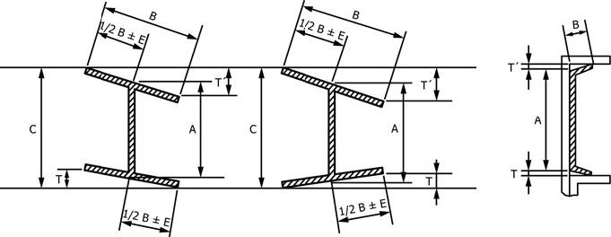
| Shape | Section Nominal Size, mm | A, Depth | B, Flange Width | T + TᴵA, Flanges Out-of-SquareB | E, Web off CenterC | C, Maximum Depth at any Cross Section over Theoretical Depth | Permitted Variations Over or Under Theoretical Web Thickness for Thicknesses Given in Millimetres, mm | |||
|---|---|---|---|---|---|---|---|---|---|---|
| Over Theoretical | Under Theoretical | Over Theoretical | Under Theoretical | 5 and Under | Over 5 | |||||
| W and HP | up to 310 | 4 | 3 | 6 | 5 | 6 | 5 | 6 | .... | .... |
| over 310, incl | 4 | 3 | 6 | 5 | 8 | 5 | 6 | .... | .... | |
| S and M | 75 to 180, incl | 2 | 2 | 3 | 3 | 0.03 | 5 | .... | .... | .... |
| over 180 to 360, incl | 3 | 2 | 4 | 4 | 0.03 | 5 | .... | .... | .... | |
| over 360 to 610, incl | 5 | 3 | 5 | 5 | 0.03 | 5 | .... | .... | .... | |
| C and MC | 40 and under | 1 | 1 | 1 | 1 | 0.03 | .... | .... | 0.2 | 0.4 |
| over 40 to 75, excl | 2 | 2 | 2 | 2 | 0.03 | .... | .... | 0.4 | 0.5 | |
| 75 to 180, incl | 3 | 2 | 3 | 3 | 0.03 | .... | .... | .... | .... | |
| over 180 to 360, incl | 3 | 3 | 3 | 4 | 0.03 | .... | .... | .... | .... | |
| over 360 | 5 | 4 | 3 | 5 | 0.03 | .... | .... | .... | .... | |
AT + Tᴵ applies when flanges of channels are toed in or out. For channels 16 mm and under in depth, the permitted out-of-square is 0.05 mm/mm of depth. The permitted variation shall be rounded to the nearest millimetre after calculation.
BPermitted variation is per millimetre of flange width for S, M, C, and MC shapes.
CPermitted variation of 8 mm max for sections over 634kg/m.
TABLE A1.17 Permitted Variations in Cross Section for Angles (L Shapes), Bulb Angles, and Zees
NOTE 1—Where “....” appears in this table, there is no requirement.
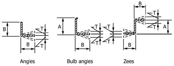
| Section | Nominal Size, mm | A, Depth | B, Flange Width, or Length of Leg | T, Out-of-Square per Millimetre of B | Permitted Variations Over or Under Theoretical Thickness for Thicknesses Given in Millimetres, mm | ||||
|---|---|---|---|---|---|---|---|---|---|
| Over Theoretical | Under Theoretical | Over Theoretical | Under Theoretical | 5 and Under | Over 5 to 10 | Over 10 | |||
| AnglesA (L shapes) | 25 and under | .... | .... | 1 | 1 | 0.026B | 0.2 | 0.2 | .... |
| Over 25 to 51, incl | .... | .... | 1 | 1 | 0.026B | 0.2 | 0.2 | 0.3 | |
| Over 51 to 64, incl | .... | .... | 2 | 2 | 0.026B | 0.3 | 0.4 | 0.4 | |
| Over 64 to 102, incl | .... | .... | 3 | 2 | 0.026B | .... | .... | .... | |
| Over 102 to 152, incl | .... | .... | 3 | 3 | 0.026B | .... | .... | .... | |
| Over 152 to 203, incl | .... | .... | 5 | 3 | 0.026B | .... | .... | .... | |
| Over 203 to 254, incl | .... | .... | 6 | 6 | 0.026B | .... | .... | .... | |
| Over 254 | .... | .... | 6 | 10 | 0.026B | .... | .... | .... | |
| Bulb angles | (depth) 76 to 102, incl | 3 | 2 | 4 | 2 | 0.026B | .... | .... | .... |
| Over 102 to 155, incl | 3 | 2 | 4 | 3 | 0.026B | .... | .... | .... | |
| Over 152 | 3 | 2 | 5 | 3 | 0.026B | .... | .... | .... | |
| Zees | 76 to 102, incl | 3 | 2 | 4 | 2 | 0.026B | .... | .... | .... |
| Over 102 to 152, incl | 3 | 2 | 4 | 3 | 0.026B | .... | .... | .... | |
AFor unequal leg angles, longer leg determines classification.
B0.026 mm/mm = 1½ °. The permitted variation shall be rounded to the nearest millimetre after calculation.
TABLE A1.18 Permitted Variations in Sectional Dimensions for Rolled Tees
NOTE 1—*Back of square and center line of stem are to be parallel when measuring “out-of-square.”
NOTE 2—Where “....” appears in this table, there is no requirement.
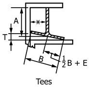
| Nominal SizeA | A, DepthB | B, WidthB | T, Out-of-Square per Millimetre of B | E, Web Off-Center, max | Stem Out-of-SquareC | Thickness of Flange | Thickness of Stem | ||||
|---|---|---|---|---|---|---|---|---|---|---|---|
| Over | Under | Over | Under | Over | Under | Over | Under | ||||
| 30 and under | 1 | 1 | 1 | 1 | .... | .... | 1 | 0.2 | 0.2 | 0.1 | 0.5 |
| Over 30 to 50, incl | 2 | 2 | 2 | 2 | .... | .... | 2 | 0.3 | 0.3 | 0.2 | 0.5 |
| Over 50 to 75, excl | 2 | 2 | 2 | 2 | .... | .... | 2 | 0.4 | 0.4 | 0.4 | 0.5 |
| 75 to 125, incl | 2 | 2 | 3 | 3 | 0.03 | 2 | .... | .... | .... | .... | .... |
| Over 125 to 180, incl | 2 | 2 | 3 | 3 | 0.03 | 3 | .... | .... | .... | .... | .... |
AThe longer member of an unequal tee determines the size for permitted variations.
BMeasurements for both depth and width are overall.
CStem out-of-square is the permitted variation from its true position of the center line of stem, measured at the point.
TABLE A1.19 Permitted Variations in Length for S, M, C, MC, L, T, Z, and Bulb Angle Shapes
NOTE 1—Where “....” appears in this table, there is no requirement.
| Nominal Size,A mm | Permitted Variations From Specified Length for Lengths Given in Metres, mm | |||||||||||||
|---|---|---|---|---|---|---|---|---|---|---|---|---|---|---|
| 1.5 to 3, excl | 3 to 6, excl | 6 to 9, incl | Over 9 to 12, incl | Over 12 to 15, incl | Over 15 to 20, incl | Over 20 m | ||||||||
| Over | Under | Over | Under | Over | Under | Over | Under | Over | Under | Over | Under | Over | Under | |
| Under 75 | 16 | 0 | 25 | 0 | 38 | 0 | 51 | 0 | 64 | 0 | 64 | 0 | .... | .... |
| 75 and over | 25 | 0 | 38 | 0 | 45 | 0 | 57 | 0 | 70 | 0 | 70 | 0 | .... | .... |
AGreatest cross-sectional dimension.
TABLE A1.20 Permitted Variations in End Out-of-Square for S, M, C, MC, L, T, Z, Bulb Angle, and Flat Bar Shapes
| Shapes | Permitted Variation |
|---|---|
| S, M, C, and MC | 0.017 mm per millimetre of depth |
| LA | 0.026 mm per millimetre of leg length or 1½ ° |
| Bulb angles | 0.026 mm per millimetre of depth or 1½ ° |
| Rolled teesA | 0.017 mm per millimetre of flange or stem |
| Zees | 0.026 mm per millimetre of sum of both flange lengths |
| Flat BarsB | 0.017 mm per millimetre of width but not less than 2 mm |
APermitted variations in ends out-of-square are determined on the longer members of the shape.
BFor flat bars, permitted variations in end out-of-square are determined on the width of the bar.
TABLE A1.21 Permitted Variations in Straightness for S, M, C, MC, L, T, Z, and Bulb Angle Shapes
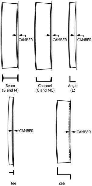
| Variable | Nominal Size,A mm | Permitted Variation, mm |
|---|---|---|
| Camber | Under 75 | 4 × number of metres of total length |
| Camber | 75 and over | 2 × number of metres of total length |
| Sweep | All | Due to the extreme variations in flexibility of these shapes, permitted variations for sweep are subject to negotiations between the manufacturer and the purchaser for the individual sections involved. |
AGreatest cross-sectional dimension.
TABLE A1.22 Permitted Variations in Length for W and HP Shapes
| Permitted Variations from Specified Length for Lengths Given in Metres, mmA, B | |
|---|---|
| Over | Under |
| 100 | 0 |
AFor HP and W shapes specified in the order for use as bearing piles, the permitted variations in length are plus 125 and minus 0 mm. These permitted variations in length also apply to sheet piles.
BThe permitted variations in end out-of-square for W and HP shapes shall be 0.016 mm per millimetre of depth, or per millimetre of flange width if the flange width is larger than the depth. The permitted variations shall be rounded to the nearest millimetre after calculation.
TABLE A1.23 Permitted Variations for Length and End Out-of-Square, Milled Shapes
| Permitted Variations in Length and End Out-of-Square, mmA | |||||||
|---|---|---|---|---|---|---|---|
| Nominal Depth, mm | Length,C m | Milled Both EndsB Length |
End Out-of-Square | Milled One EndB Length |
End Out-of-Square-(for Milled End) | ||
| Over | Under | Over | Under | ||||
| 150 to 920 | 2 to 21 | 1 | 1 | 1 | 6 | 6 | 1 |
AThe permitted variations in length and end out-of-square are additive.
BEnd out-of-square is measured by (a) squaring from the center line of the web and (b) squaring from the center line of the flange. The measured variation from true squareness in either plane shall not exceed the total tabular amount.
CLength is measured along center line of web. Measurements are made with the steel and tape at the same temperature.
TABLE A1.24 Permitted Variations in Straightness for W and HP Shapes
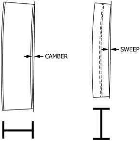
Positions for Measuring Camber and Sweep of W and HP Shapes
| Camber and sweep | Permitted Variation in Straightness, mm |
|---|---|
| General case | 1 × number of metres of total lengthA |
| When certain sectionsB with a flange width approximately equal to depth are specified in the order for use as columns: | |
| Lengths over 14 m and under | 1 × number of metres of total length, but not over 10 |
| Lengths of 14 m | 10 + [1 × (number of metres of total length – 14 m)] |
ASections with a flange width less than 150 mm, permitted variation for sweep, mm = 2 × number of metres of total length.
BApplies only to:
200-mm deep sections—46.1 kg/m and heavier,
250-mm deep sections—73 kg/m and heavier,
310-mm deep sections—97 kg/m and heavier,
360-mm deep sections—116 kg/m and heavier,
410-mm deep sections—131 kg/m and heavier, and
460-mm deep sections—202 kg/m and heavier.
For other sections specified in the order for use as columns, the permitted variation is subject to negotiation with the manufacturer.
TABLE A1.25 Permitted Variations in Dimensions for Split Tees and Split Angles (L Shapes)A
| Specified Depth, mm | Permitted Variation Over or Under Specified Depth,B mm |
|---|---|
| To 150, excl (beams and channels) | 3 |
| 150 to 410, excl (beams and channels) | 5 |
| 410 to 510, excl (beams and channels) | 6 |
| 510 to 610, excl (beams) | 8 |
| 610 and over (beams) | 10 |
AThe permitted variations in length for split tees or angles are the same as those applicable to the section from which the tees or angles are split.
BThe above permitted variations in depth of tees or angles include the permitted variations in depth for the beams or channels before splitting. Permitted variations in dimensions and straightness, as set up for the beams or channels from which these tees or angles are cut, apply, except
straightness = 2 mm × length in metres
TABLE A1.26 Permitted Variations in Sectional Dimensions for Square-Edge and Round-Edge Flat Bars
NOTE 1—Where “....” appears in this table, there is no requirement.
| Specified Widths, mm | Permitted Variations Over or Under Specified Thickness, for Thicknesses Given in Millimetres, mm | Permitted Variations from Specified Width, mm | ||||||
|---|---|---|---|---|---|---|---|---|
| Over 5 to 6, incl | Over 6 to 12, incl | Over 12 to 25, incl | Over 25 to 50, incl | Over 50 to 75 | Over 75 | Over | Under | |
| To 25, incl | 0.18 | 0.20 | 0.25 | .... | .... | .... | 0.5 | 0.5 |
| Over 25 to 50, incl | 0.18 | 0.30 | 0.40 | 0.8 | .... | .... | 1.0 | 1.0 |
| Over 50 to 100, incl | 0.20 | 0.40 | 0.50 | 0.8 | 1.2 | 1.2 | 1.5 | 1.0 |
| Over 100 to 150, incl | 0.25 | 0.40 | 0.50 | 0.8 | 1.2 | 1.2 | 2.5 | 1.5 |
| Over 150 to 200, incl | A | 0.40 | 0.65 | 0.8 | 1.2 | 1.6 | 3.0 | 2.5 |
AFlats over 150 to 200 mm, incl, in width are not available as hot-rolled bars in thickness 6 mm and under.
TABLE A1.27 Permitted Variations in Sectional Dimensions for Round and Square Bars and Round-Cornered Squares
NOTE 1—Where “....” appears in this table, there is no requirement.
| Specified Sizes, mm | Permitted Variation Over or Under Specified Size | Permitted Out-of-Round or Out-of-Square SectionA | ||
|---|---|---|---|---|
| mm | % | mm | % | |
| Up to 7.0, incl | 0.13 | .... | 0.20 | .... |
| Over 7.0 to 11.0, incl | 0.15 | .... | 0.22 | .... |
| Over 11.0 to 15.0, incl | 0.18 | .... | 0.27 | .... |
| Over 15.0 to 19.0, incl | 0.20 | .... | 0.30 | .... |
| Over 19.0 to 250, incl | .... | 1B | .... | 1½B |
AOut-of-round is the difference between the maximum and minimum diameters of the bar, measured at the same transverse cross section. Out-of-square section is the difference in perpendicular distance between opposite faces, measured at the same transverse cross section.
BThe permitted variation shall be rounded to the nearest tenth of a millimetre after calculation.
TABLE A1.28 Permitted Variations in Sectional Dimensions for Hexagons
| Specified Sizes Between Opposite Sides, mm | Permitted Variations from Specified Size, mm | Out-of-Hexagon Section, mmA | |
|---|---|---|---|
| Over | Under | ||
| To 13 incl | 0.18 | 0.18 | 0.3 |
| Over 13 to 25 incl | 0.25 | 0.25 | 0.4 |
| Over 25 to 40 incl | 0.55 | 0.35 | 0.6 |
| Over 40 to 50 incl | 0.8 | 0.40 | 0.8 |
| Over 50 to 65 incl | 1.2 | 0.40 | 1.2 |
| Over 65 to 80 incl | 1.6 | 1.6 | |
AOut-of-hexagon section is the greatest difference in distance between any two opposite faces, measured at the same transverse cross section.
TABLE A1.29 Permitted Variations in Straightness for Bars
| Maximum Permitted Variation in Straightness, mmA |
|---|
| 6 mm in any 1500 mm and (length in millimetres/250)B |
APermitted variations in straightness do not apply to hot-rolled bars if any subsequent heating operation has been performed.
BRound to the nearest whole millimetre.
TABLE A1.30 Permitted Variations in Length for Hot-Cut Steel BarsA
NOTE 1—Where “....” appears in this table, there is no requirement.
| Specified Sizes of Rounds, Squares, and Hexagons, mm | Specified Sizes of Flats, mm | Permitted Variations Over Specified Lengths Given in Metres, mm (No Variation Under) | |||||
|---|---|---|---|---|---|---|---|
| Thickness | Width | 1.5 to 3, excl | 3 to 6, excl | 6 to 9, excl | 9 to 12, excl | 12 to 18, incl | |
| To 25, incl | to 25, incl | to 75, incl | 15 | 20 | 35 | 45 | 60 |
| Over 25 to 50, incl | over 25 | to 75, incl | 15 | 25 | 40 | 50 | 65 |
| Over 25 to 50, incl | to 25, incl | over 75 to 150, incl | 15 | 25 | 40 | 50 | 65 |
| Over 50 to 125, incl | over 25 | over 75 to 150, incl | 25 | 40 | 45 | 60 | 70 |
| Over 125 to 250, incl | .... | .... | 50 | 65 | 70 | 75 | 85 |
| over 6 to 25, incl | over 150 to 200, incl | 20 | 30 | 45 | 90 | 100 | |
| over 25 to 75, incl | over 150 to 200, incl | 30 | 45 | 50 | 90 | 100 | |
| Bar size sections | .... | .... | 15 | 25 | 40 | 50 | 65 |
| Hot Sawing | |||||||
| 50 to 125, incl | 25 and over | 75 and over | B | 40 | 45 | 60 | 70 |
| Over 125 to 250, incl | .... | .... | B | 65 | 70 | 75 | 85 |
AFor flats over 150 to 200 mm, incl, in width and over 75 mm in thickness, consult the manufacturer for permitted variations in length.
BSmaller sizes and shorter lengths are not commonly hot sawed.
TABLE A1.31 Permitted Variations in Length for Bars Recut Both Ends After StraighteningA,B
| Sizes of Rounds, Squares, Hexagons, Widths of Flats and Maximum Dimensions of Other Sections, mm | Permitted Variations Over Specified Length Given in Metres, mm (No Variation Under) | |
|---|---|---|
| to 3.7, incl | over 3.7 | |
| To 75, incl | 6 | 8 |
| Over 75 to 150, incl | 8 | 11 |
| Over 150 to 200, incl | 11 | 14 |
| Rounds over 200 to 250, incl | 14 | 18 |
AFor flats over 150 to 200 mm, incl, in width, and over 75 mm in thickness, consult the manufacturer or the processor for permitted variations in length.
BPermitted variations are sometimes required all over or all under the specified length, in which case the sum of the two permitted variations applies.
A2. DIMENSIONS OF STANDARD SHAPE PROFILES
A2.1 Listed herein are dimensions and weight [mass] of some standard shape profiles. The values stated in inch-pound units are independent of the values stated in SI units, and the values from the two systems are not to be combined in any way. Unless the order specifies the applicable “M” specification designation (SI units), the material shall be furnished to inch-pound units.
TABLE A2.1 “W” Shapes

| Designation (Nominal Depth in Inches and Weight in Pounds per Linear Foot) | Area Ar in.2 | Depth dr in. | Flange | Web Thickness tw, in.A | Designation [Nominal Depth in Millimetres and Mass in Kilograms per Metre] | Area Ar mm2 | Depth dr mm | Flange | Web Thickness twA mm | ||
|---|---|---|---|---|---|---|---|---|---|---|---|
| Width bf in. | Thickness tf in.A | Width bf mm | Thickness tfA mm | ||||||||
| W44 × 408 | 120.5 | 44.80 | 16.142 | 2.165 | 1.220 | W1100 × 607 | 77 740 | 1 138 | 410 | 55.0 | 31.0 |
| × 368 | 108.9 | 44.41 | 16.024 | 1.969 | 1.102 | × 548 | 70 250 | 1 128 | 407 | 50.0 | 28.0 |
| × 335 | 98.7 | 44.02 | 15.945 | 1.770 | 1.025 | × 499 | 63 500 | 1 118 | 405 | 45.0 | 26.0 |
| × 290 | 85.8 | 43.62 | 15.825 | 1.575 | 0.865 | × 433 | 55 100 | 1 108 | 402 | 40.0 | 22.0 |
| × 262 | 77.2 | 43.31 | 15.750 | 1.415 | 0.785 | × 390 | 49 700 | 1 100 | 400 | 36.0 | 20.0 |
| × 230 | 67.9 | 42.91 | 15.750 | 1.220 | 0.710 | × 343 | 43 600 | 1 090 | 400 | 31.0 | 18.0 |
| W40 × 655 | 192.6 | 43.62 | 16.870 | 3.540 | 1.970 | W1000 × 976 | 124 300 | 1 108 | 428 | 89.9 | 50.0 |
| × 593 | 174.4 | 42.99 | 16.690 | 3.230 | 1.790 | × 883 | 112 500 | 1 092 | 424 | 82.0 | 45.5 |
| × 503 | 147.8 | 42.05 | 16.415 | 2.755 | 1.535 | × 748 | 95 300 | 1 068 | 417 | 70.0 | 39.0 |
| × 431 | 126.7 | 41.26 | 16.220 | 2.360 | 1.340 | × 642 | 81 800 | 1 048 | 412 | 60.0 | 34.0 |
| × 397 | 117.0 | 40.95 | 16.120 | 2.200 | 1.220 | × 591 | 75 300 | 1 040 | 409 | 55.9 | 31.0 |
| × 372 | 109.4 | 40.63 | 16.065 | 2.045 | 1.160 | × 554 | 70 600 | 1 032 | 408 | 52.1 | 29.5 |
| × 362 | 107.0 | 40.55 | 16.020 | 2.010 | 1.120 | × 539 | 68 700 | 1 030 | 407 | 51.0 | 28.4 |
| × 324 | 95.3 | 40.16 | 15.910 | 1.810 | 1.000 | × 483 | 61 500 | 1 020 | 404 | 46.0 | 25.4 |
| × 297 | 87.4 | 39.84 | 15.825 | 1.650 | 0.930 | × 443 | 56 400 | 1 012 | 402 | 41.9 | 23.6 |
| × 277 | 81.3 | 39.69 | 15.830 | 1.575 | 0.830 | × 412 | 52 500 | 1 008 | 402 | 40.0 | 21.1 |
| × 249 | 73.3 | 39.38 | 15.750 | 1.420 | 0.750 | × 371 | 47 300 | 1 000 | 400 | 36.1 | 19.0 |
| × 215 | 63.3 | 38.98 | 15.750 | 1.220 | 0.650 | × 321 | 40 800 | 990 | 400 | 31.0 | 16.5 |
| × 199 | 58.4 | 38.67 | 15.750 | 1.065 | 0.650 | × 296 | 37 700 | 982 | 400 | 27.1 | 16.5 |
| W40 × 392 | 115.3 | 41.57 | 12.360 | 2.520 | 1.415 | W1000 × 584 | 74 400 | 1 056 | 314 | 64.0 | 36.0 |
| × 331 | 97.5 | 40.79 | 12.165 | 2.125 | 1.220 | × 494 | 62 900 | 1 036 | 309 | 54.0 | 31.0 |
| × 327 | 95.9 | 40.79 | 12.130 | 2.130 | 1.180 | × 486 | 61 900 | 1 036 | 308 | 54.1 | 30.0 |
| × 294 | 86.2 | 40.39 | 12.010 | 1.930 | 1.060 | × 438 | 55 600 | 1 026 | 305 | 49.0 | 26.9 |
| × 278 | 81.9 | 40.16 | 11.970 | 1.810 | 1.025 | × 415 | 52 800 | 1 020 | 304 | 46.0 | 26.0 |
| × 264 | 77.6 | 40.00 | 11.930 | 1.730 | 0.960 | × 393 | 50 100 | 1 016 | 303 | 43.9 | 24.4 |
| × 235 | 68.9 | 39.69 | 11.890 | 1.575 | 0.830 | × 350 | 44 600 | 1 008 | 302 | 40.0 | 21.1 |
| × 211 | 62.0 | 39.37 | 11.810 | 1.415 | 0.750 | × 314 | 40 000 | 1 000 | 300 | 35.9 | 19.1 |
| × 183 | 53.7 | 38.98 | 11.810 | 1.200 | 0.650 | × 272 | 34 600 | 990 | 300 | 31.0 | 16.5 |
| × 167 | 49.1 | 38.59 | 11.810 | 1.025 | 0.650 | × 249 | 31 700 | 980 | 300 | 26.0 | 16.5 |
| × 149 | 43.8 | 38.20 | 11.810 | 0.830 | 0.630 | × 222 | 28 200 | 970 | 300 | 21.1 | 16.0 |
| W36 × 925 | 271.9 | 43.05 | 18.620 | 4.530 | 3.020 | W920 × 1377 | 175 400 | 1 093 | 473 | 115.1 | 76.7 |
| × 853 | 250.6 | 43.05 | 18.150 | 4.530 | 2.520 | × 1269 | 161 700 | 1 093 | 461 | 115.1 | 64.0 |
| × 802 | 235.9 | 42.57 | 17.990 | 4.290 | 2.380 | × 1194 | 152 200 | 1 081 | 457 | 109.0 | 60.5 |
| × 723 | 212.7 | 41.79 | 17.755 | 3.900 | 2.165 | × 1077 | 137 200 | 1 061 | 451 | 99.1 | 55.0 |
| × 652 | 191.7 | 41.05 | 17.575 | 3.540 | 1.970 | × 970 | 123 700 | 1 043 | 446 | 89.9 | 50.0 |
| × 529 | 155.6 | 39.79 | 17.220 | 2.910 | 1.610 | × 787 | 100 400 | 1 011 | 437 | 73.9 | 40.9 |
| × 487 | 143.2 | 39.33 | 17.105 | 2.680 | 1.500 | × 725 | 92 400 | 999 | 434 | 68.1 | 38.1 |
| × 441 | 129.7 | 38.85 | 16.965 | 2.440 | 1.360 | × 656 | 83 700 | 987 | 431 | 62.0 | 34.5 |
TABLE A2.1 Continued
| Designation (Nominal Depth in Inches and Weight in Pounds per Linear Foot) | Area Ar in.2 | Depth dr in. | Flange | Web Thickness tw, in.A | Designation [Nominal Depth in Millimetres and Mass in Kilograms per Metre] | Area Ar mm2 | Depth dr mm | Flange | Web Thickness twA mm | ||
|---|---|---|---|---|---|---|---|---|---|---|---|
| Width bf in. | Thickness tf in.A | Width bf mm | Thickness tfA mm | ||||||||
| × 395 | 116.2 | 38.37 | 16.830 | 2.200 | 1.220 | W920 × 588 | 75 000 | 975 | 427 | 55.9 | 31.0 |
| × 361 | 106.1 | 37.99 | 16.730 | 2.010 | 1.120 | × 537 | 68 500 | 965 | 425 | 51.1 | 28.4 |
| × 330 | 97.0 | 37.67 | 16.630 | 1.850 | 1.020 | × 491 | 62 600 | 957 | 422 | 47.0 | 25.9 |
| × 302 | 88.8 | 37.33 | 16.585 | 1.680 | 0.945 | × 449 | 57 600 | 948 | 423 | 42.7 | 24.0 |
| × 282 | 82.9 | 37.11 | 16.550 | 1.540 | 0.885 | × 420 | 53 700 | 943 | 420 | 39.6 | 22.5 |
| × 262 | 77.0 | 36.85 | 16.595 | 1.470 | 0.840 | × 390 | 49 500 | 936 | 422 | 36.9 | 21.3 |
| × 247 | 72.5 | 36.67 | 16.570 | 1.350 | 0.800 | × 368 | 46 800 | 931 | 419 | 34.3 | 20.3 |
| × 231 | 68.0 | 36.49 | 16.410 | 1.260 | 0.760 | × 344 | 43 600 | 927 | 419 | 32.0 | 19.3 |
| W36 × 387 | 113.6 | 39.09 | 12.677 | 2.559 | 1.421 | W920 × 576 | 73 320 | 993 | 322 | 65.0 | 36.1 |
| × 350 | 102.9 | 38.62 | 12.559 | 2.319 | 1.299 | × 521 | 66 370 | 981 | 319 | 58.9 | 33.0 |
| × 316 | 93.6 | 38.23 | 12.441 | 2.192 | 1.181 | × 474 | 60 390 | 971 | 316 | 54.1 | 30.0 |
| × 288 | 84.0 | 37.83 | 12.223 | 1.929 | 1.059 | × 425 | 54 200 | 961 | 313 | 49.0 | 26.9 |
| × 256 | 75.4 | 37.43 | 12.125 | 1.730 | 0.970 | × 381 | 48 600 | 951 | 310 | 43.9 | 24.4 |
| × 232 | 68.1 | 37.12 | 12.210 | 1.570 | 0.860 | × 345 | 44 000 | 943 | 308 | 39.9 | 22.1 |
| × 210 | 61.8 | 36.69 | 12.115 | 1.360 | 0.835 | × 313 | 39 900 | 932 | 309 | 34.5 | 21.1 |
| × 194 | 57.0 | 36.49 | 12.180 | 1.260 | 0.765 | × 289 | 36 800 | 927 | 308 | 32.0 | 19.4 |
| × 182 | 53.6 | 36.33 | 12.075 | 1.180 | 0.725 | × 271 | 34 600 | 923 | 307 | 30.0 | 18.4 |
| × 170 | 50.0 | 36.17 | 12.030 | 1.100 | 0.680 | × 253 | 32 300 | 919 | 307 | 27.9 | 17.3 |
| × 182 | 53.6 | 36.33 | 12.075 | 1.180 | 0.725 | × 271 | 34 600 | 923 | 307 | 30.0 | 18.4 |
| × 170 | 50.0 | 36.17 | 12.030 | 1.100 | 0.680 | × 253 | 32 300 | 919 | 307 | 27.9 | 17.3 |
| × 160 | 47.0 | 35.85 | 12.000 | 1.020 | 0.625 | × 238 | 30 300 | 911 | 305 | 25.9 | 15.9 |
| × 150 | 44.2 | 35.01 | 11.975 | 0.940 | 0.625 | × 223 | 28 500 | 915 | 304 | 23.9 | 16.5 |
| × 135 | 39.7 | 35.55 | 11.950 | 0.790 | 0.600 | × 201 | 25 600 | 903 | 304 | 20.1 | 15.2 |
| Designation (Nominal Depth in Inches and Weight in Pounds per Linear Foot) | Area Ar in.2 | Depth dr in. | Flange | Web Thickness tw, in.A | Designation [Nominal Depth in Millimetres and Mass in Kilograms per Metre] | Area Ar mm2 | Depth dr mm | Flange | Web Thickness twA mm | ||
| Width bf in. | Thickness tf in.A | Width bf mm | Thickness tfA mm | ||||||||
| W33 × 387 | 114.0 | 35.95 | 16.200 | 2.280 | 1.260 | W840 × 576 | 73 500 | 913 | 411 | 57.9 | 32.0 |
| × 354 | 104.1 | 35.55 | 16.100 | 2.090 | 1.160 | × 527 | 67 200 | 903 | 409 | 53.1 | 29.5 |
| × 318 | 93.5 | 35.16 | 15.985 | 1.890 | 1.040 | × 473 | 60 300 | 893 | 406 | 48.0 | 26.4 |
| × 291 | 85.6 | 34.84 | 15.905 | 1.730 | 0.960 | × 433 | 55 200 | 885 | 404 | 43.9 | 24.4 |
| × 263 | 77.4 | 34.53 | 15.805 | 1.570 | 0.870 | × 392 | 49 900 | 877 | 401 | 39.9 | 22.1 |
| × 241 | 70.9 | 34.18 | 15.860 | 1.400 | 0.830 | × 359 | 45 700 | 868 | 403 | 35.6 | 21.1 |
| × 221 | 65.0 | 33.93 | 15.805 | 1.275 | 0.775 | × 329 | 41 900 | 862 | 401 | 32.4 | 19.7 |
| × 201 | 59.1 | 33.68 | 15.745 | 1.150 | 0.715 | × 299 | 38 100 | 855 | 400 | 29.2 | 18.2 |
| W33 × 169 | 49.5 | 33.82 | 11.500 | 1.220 | 0.670 | W840 × 251 | 31 900 | 859 | 292 | 31.0 | 17.0 |
| × 152 | 44.7 | 33.49 | 11.565 | 1.055 | 0.635 | × 226 | 28 800 | 851 | 294 | 26.8 | 16.1 |
| × 141 | 41.6 | 33.30 | 11.535 | 0.960 | 0.605 | × 210 | 26 800 | 846 | 293 | 24.4 | 15.4 |
| × 130 | 38.3 | 33.09 | 11.510 | 0.855 | 0.580 | × 193 | 24 700 | 840 | 292 | 21.7 | 14.7 |
| × 118 | 34.7 | 32.86 | 11.480 | 0.740 | 0.550 | × 176 | 22 400 | 835 | 292 | 18.8 | 14.0 |
| W30 × 391 | 115.0 | 33.19 | 15.590 | 2.440 | 1.360 | W760 × 582 | 74 200 | 843 | 396 | 62.0 | 34.5 |
| × 357 | 104.8 | 32.80 | 15.470 | 2.240 | 1.240 | × 531 | 67 600 | 833 | 393 | 56.9 | 31.5 |
| × 326 | 95.7 | 32.40 | 15.370 | 2.050 | 1.140 | × 484 | 61 700 | 823 | 390 | 52.1 | 29.0 |
| × 292 | 85.7 | 32.01 | 15.255 | 1.850 | 1.020 | × 434 | 55 300 | 813 | 387 | 47.0 | 25.9 |
| × 261 | 76.7 | 31.61 | 15.155 | 1.650 | 0.930 | × 389 | 49 500 | 803 | 385 | 41.9 | 23.6 |
| × 235 | 69.0 | 31.30 | 15.055 | 1.500 | 0.830 | × 350 | 44 500 | 795 | 382 | 38.1 | 21.1 |
| × 211 | 62.0 | 30.94 | 15.105 | 1.315 | 0.775 | × 314 | 40 000 | 786 | 384 | 33.4 | 19.7 |
| × 191 | 56.1 | 30.68 | 15.040 | 1.185 | 0.710 | × 284 | 36 200 | 779 | 382 | 30.1 | 18.0 |
| × 173 | 50.8 | 30.44 | 14.985 | 1.065 | 0.655 | × 257 | 32 800 | 773 | 381 | 27.1 | 16.6 |
| W30 × 148 | 43.5 | 30.67 | 10.480 | 1.180 | 0.650 | W760 × 220 | 28 100 | 779 | 266 | 30.0 | 16.5 |
| × 132 | 38.9 | 30.31 | 10.545 | 1.000 | 0.615 | × 196 | 25 100 | 770 | 268 | 25.4 | 15.6 |
| × 124 | 36.5 | 30.17 | 10.515 | 0.930 | 0.585 | × 185 | 23 500 | 766 | 267 | 23.6 | 14.9 |
| × 116 | 34.2 | 30.01 | 10.495 | 0.850 | 0.565 | × 173 | 22 100 | 762 | 267 | 21.6 | 14.4 |
| × 108 | 31.7 | 29.83 | 10.475 | 0.760 | 0.545 | × 161 | 20 500 | 758 | 266 | 19.3 | 13.8 |
| × 99 | 29.1 | 29.65 | 10.450 | 0.670 | 0.520 | × 147 | 18 800 | 753 | 265 | 17.0 | 13.2 |
| × 90 | 26.4 | 29.53 | 10.400 | 0.610 | 0.470 | × 134 | 17 000 | 750 | 264 | 15.5 | 11.9 |
| W27 × 539 | 158.4 | 32.52 | 15.255 | 3.540 | 1.970 | W690 × 802 | 102 200 | 826 | 387 | 89.9 | 50.0 |
| × 368 | 108.1 | 30.39 | 14.665 | 2.480 | 1.380 | × 548 | 69 800 | 772 | 372 | 63.0 | 35.1 |
| × 336 | 98.7 | 30.0 | 14.550 | 2.280 | 1.260 | × 500 | 63 700 | 762 | 369 | 57.9 | 32.0 |
| × 307 | 90.2 | 29.61 | 14.445 | 2.090 | 1.160 | × 457 | 58 200 | 752 | 367 | 53.1 | 29.5 |
| × 281 | 82.6 | 29.29 | 14.350 | 1.930 | 1.060 | × 419 | 53 300 | 744 | 364 | 49.0 | 26.9 |
| × 258 | 75.7 | 28.98 | 14.270 | 1.770 | 0.980 | × 384 | 48 900 | 736 | 362 | 45.0 | 24.9 |
| × 235 | 69.1 | 28.66 | 14.190 | 1.610 | 0.910 | × 350 | 44 600 | 728 | 360 | 40.9 | 23.1 |
| × 217 | 63.8 | 28.43 | 14.115 | 1.500 | 0.830 | × 323 | 41 100 | 722 | 359 | 38.1 | 21.1 |
| × 194 | 57.0 | 28.11 | 14.035 | 1.340 | 0.750 | × 289 | 36 800 | 714 | 356 | 34.0 | 19.0 |
| × 178 | 52.3 | 27.81 | 14.085 | 1.190 | 0.725 | × 265 | 33 700 | 706 | 358 | 30.2 | 18.4 |
| × 161 | 47.4 | 27.59 | 14.020 | 1.080 | 0.660 | × 240 | 30 600 | 701 | 356 | 27.4 | 16.8 |
| × 146 | 42.9 | 27.38 | 13.965 | 0.975 | 0.605 | × 217 | 27 700 | 695 | 355 | 24.8 | 15.4 |
| W27 × 129 | 37.8 | 27.63 | 10.010 | 1.100 | 0.610 | W690 × 192 | 24 400 | 702 | 254 | 27.9 | 15.5 |
| × 114 | 33.5 | 27.29 | 10.070 | 0.930 | 0.570 | × 170 | 21 600 | 693 | 256 | 23.6 | 14.5 |
| × 102 | 30.0 | 26.92 | 10.015 | 0.835 | 0.515 | × 152 | 19 400 | 684 | 254 | 21.1 | 13.1 |
| × 94 | 27.7 | 26.92 | 9.990 | 0.745 | 0.490 | × 140 | 17 900 | 684 | 253 | 18.9 | 12.4 |
| × 84 | 24.8 | 26.71 | 9.960 | 0.640 | 0.460 | × 125 | 16 000 | 678 | 253 | 16.3 | 11.7 |
| W24 × 370 | 108.0 | 27.99 | 13.660 | 2.720 | 1.520 | W610 × 551 | 70 200 | 711 | 347 | 69.1 | 38.6 |
| × 335 | 98.4 | 27.52 | 13.520 | 2.480 | 1.380 | × 498 | 63 500 | 699 | 343 | 63.0 | 35.1 |
| × 306 | 89.8 | 27.13 | 13.405 | 2.220 | 1.260 | × 455 | 57 000 | 689 | 340 | 56.5 | 32.0 |
| × 279 | 82.0 | 26.73 | 13.305 | 2.090 | 1.160 | × 415 | 52 400 | 679 | 338 | 53.1 | 29.5 |
| × 250 | 73.5 | 26.34 | 13.185 | 1.890 | 1.040 | × 372 | 47 400 | 669 | 335 | 48.0 | 26.4 |
| × 229 | 67.2 | 26.02 | 13.115 | 1.730 | 0.960 | × 341 | 43 400 | 661 | 333 | 43.9 | 24.4 |
| × 207 | 60.7 | 25.71 | 13.010 | 1.570 | 0.870 | × 307 | 39 100 | 653 | 330 | 39.9 | 22.1 |
| × 192 | 56.3 | 25.47 | 12.950 | 1.460 | 0.810 | × 285 | 36 100 | 647 | 329 | 37.1 | 20.6 |
| × 176 | 51.7 | 25.24 | 12.880 | 1.340 | 0.750 | × 262 | 33 300 | 641 | 327 | 34.0 | 19.1 |
| × 162 | 47.7 | 25.00 | 12.955 | 1.220 | 0.705 | × 241 | 30 800 | 635 | 329 | 31.0 | 17.9 |
| × 146 | 43.0 | 24.74 | 12.905 | 1.090 | 0.650 | × 217 | 27 900 | 628 | 328 | 27.7 | 16.5 |
| × 131 | 38.5 | 24.48 | 12.855 | 0.960 | 0.605 | × 195 | 24 800 | 622 | 327 | 24.4 | 15.4 |
| × 117 | 34.4 | 24.26 | 12.800 | 0.850 | 0.550 | × 174 | 22 200 | 616 | 325 | 21.6 | 14.0 |
| × 104 | 30.6 | 24.06 | 12.750 | 0.750 | 0.500 | × 155 | 19 700 | 611 | 324 | 19.0 | 12.7 |
| W24 × 103 | 30.3 | 24.53 | 9.000 | 0.980 | 0.550 | W610 × 153 | 19 600 | 623 | 229 | 24.9 | 14.0 |
| × 94 | 27.7 | 24.33 | 9.065 | 0.875 | 0.515 | × 140 | 19 000 | 617 | 230 | 22.2 | 13.1 |
| × 84 | 24.7 | 24.10 | 9.020 | 0.770 | 0.470 | × 125 | 15 900 | 612 | 229 | 19.6 | 11.9 |
| × 76 | 22.4 | 23.92 | 8.990 | 0.680 | 0.440 | × 113 | 14 500 | 608 | 228 | 17.3 | 11.2 |
| × 68 | 20.1 | 23.73 | 8.965 | 0.585 | 0.415 | × 101 | 13 000 | 603 | 228 | 14.9 | 10.5 |
| W24 × 62 | 18.2 | 23.74 | 7.040 | 0.590 | 0.430 | W610 × 92 | 11 700 | 603 | 179 | 15.0 | 10.9 |
| × 55 | 16.2 | 23.57 | 7.005 | 0.505 | 0.395 | × 82 | 10 500 | 599 | 178 | 12.8 | 10.0 |
| W21 × 275 | 80.9 | 24.14 | 12.890 | 2.190 | 1.220 | W530 × 409 | 52 200 | 613 | 327 | 55.6 | 31.0 |
| × 248 | 72.9 | 23.73 | 12.775 | 1.990 | 1.100 | × 369 | 47 000 | 603 | 324 | 50.5 | 27.9 |
| × 223 | 65.6 | 23.35 | 12.675 | 1.780 | 0.991 | × 332 | 42 300 | 593 | 322 | 45.1 | 25.4 |
| × 201 | 59.2 | 23.03 | 12.575 | 1.630 | 0.910 | × 300 | 38 200 | 585 | 319 | 41.4 | 23.1 |
| × 182 | 53.7 | 22.72 | 12.500 | 1.480 | 0.830 | × 272 | 34 600 | 577 | 317 | 37.6 | 21.1 |
| × 166 | 48.9 | 22.48 | 12.410 | 1.350 | 0.720 | × 219 | 29 900 | 571 | 316 | 34.3 | 18.3 |
| × 147 | 43.2 | 22.06 | 12.510 | 1.155 | 0.720 | × 196 | 25 000 | 564 | 318 | 29.2 | 18.3 |
| × 132 | 38.8 | 21.83 | 12.440 | 1.036 | 0.650 | × 182 | 23 300 | 551 | 316 | 26.4 | 16.5 |
| × 122 | 35.9 | 21.68 | 12.390 | 0.960 | 0.600 | × 165 | 21 100 | 546 | 315 | 24.4 | 15.2 |
| × 111 | 32.7 | 21.51 | 12.340 | 0.875 | 0.550 | × 155 | 19 200 | 543 | 313 | 22.2 | 14.0 |
| × 101 | 29.8 | 21.36 | 12.290 | 0.800 | 0.500 | ||||||
| W21 × 93 | 27.3 | 21.62 | 8.420 | 0.930 | 0.580 | W530 × 138 | 17 600 | 549 | 214 | 23.6 | 14.7 |
| × 83 | 24.3 | 21.43 | 8.355 | 0.835 | 0.515 | × 123 | 15 700 | 544 | 212 | 21.2 | 13.1 |
| × 73 | 21.5 | 21.24 | 8.295 | 0.745 | 0.440 | × 109 | 13 900 | 539 | 211 | 18.9 | 11.3 |
| × 68 | 20.0 | 21.13 | 8.270 | 0.685 | 0.430 | × 101 | 12 900 | 537 | 210 | 17.4 | 10.9 |
| × 62 | 18.3 | 20.99 | 8.240 | 0.622 | 0.400 | × 92 | 11 800 | 533 | 209 | 15.6 | 10.2 |
| × 55 | 16.2 | 20.80 | 8.220 | 0.515 | 0.375 | × 82 | 10 500 | 528 | 207 | 13.3 | 9.5 |
| × 48 | 14.1 | 20.62 | 8.140 | 0.430 | 0.350 | × 72 | 9 180 | 524 | 207 | 10.9 | 9.0 |
| W21 × 57 | 16.7 | 21.06 | 6.555 | 0.650 | 0.405 | W530 × 85 | 10 800 | 535 | 166 | 16.5 | 10.3 |
| × 50 | 14.7 | 20.83 | 6.530 | 0.535 | 0.380 | × 74 | 9 480 | 529 | 166 | 13.6 | 9.7 |
| × 44 | 13.0 | 20.66 | 6.500 | 0.455 | 0.350 | × 66 | 8 390 | 525 | 165 | 11.4 | 8.9 |
| W18 × 311 | 91.5 | 22.32 | 12.005 | 2.740 | 1.520 | W460 × 464 | 59 700 | 567 | 305 | 69.6 | 38.6 |
| × 283 | 83.2 | 21.85 | 11.890 | 2.500 | 1.400 | × 421 | 53 700 | 555 | 302 | 63.5 | 35.6 |
| × 258 | 75.9 | 21.46 | 11.770 | 2.250 | 1.280 | × 384 | 48 900 | 546 | 299 | 57.1 | 32.5 |
| × 234 | 68.8 | 21.08 | 11.650 | 2.110 | 1.160 | × 348 | 44 400 | 536 | 296 | 53.6 | 29.5 |
| × 211 | 62.1 | 20.71 | 11.550 | 1.940 | 1.060 | × 315 | 40 600 | 526 | 294 | 49.3 | 26.9 |
| × 192 | 56.4 | 20.37 | 11.455 | 1.750 | 0.960 | × 286 | 36 900 | 517 | 291 | 44.4 | 24.4 |
| × 175 | 51.3 | 20.04 | 11.375 | 1.580 | 0.890 | × 260 | 33 100 | 509 | 289 | 40.1 | 22.6 |
| × 158 | 46.3 | 19.72 | 11.220 | 1.440 | 0.810 | × 235 | 29 900 | 501 | 287 | 36.6 | 20.6 |
| × 143 | 42.1 | 19.49 | 11.200 | 1.320 | 0.730 | × 213 | 27 100 | 495 | 285 | 33.5 | 18.5 |
| × 130 | 38.2 | 19.25 | 11.165 | 1.200 | 0.670 | × 193 | 24 700 | 489 | 283 | 30.5 | 17.0 |
| × 119 | 35.1 | 18.97 | 11.200 | 1.060 | 0.655 | × 177 | 22 600 | 482 | 286 | 26.9 | 16.6 |
| × 106 | 31.1 | 18.73 | 11.145 | 0.940 | 0.590 | × 158 | 20 100 | 476 | 284 | 23.9 | 15.0 |
| × 97 | 28.5 | 18.59 | 11.200 | 0.870 | 0.535 | × 144 | 18 400 | 472 | 283 | 22.1 | 13.6 |
| × 86 | 25.3 | 18.39 | 11.090 | 0.770 | 0.480 | × 128 | 16 300 | 467 | 282 | 19.6 | 12.2 |
| × 76 | 22.3 | 18.21 | 11.035 | 0.680 | 0.425 | × 113 | 14 400 | 463 | 280 | 17.3 | 10.8 |
TABLE A2.1 Continued
| Designation (Nominal Depth in Inches and Weight in Pounds per Linear Foot) | Area Ar in.2 | Depth dr in. | Flange | Web Thickness tw, in.A | Designation [Nominal Depth in Millimetres and Mass in Kilograms per Metre] | Area Ar mm2 | Depth dr mm | Flange | Web Thickness twA mm | ||
|---|---|---|---|---|---|---|---|---|---|---|---|
| Width bf in. | Thickness tf in.A | Width bf mm | Thickness tfA mm | ||||||||
| W18 × 71 | 20.8 | 18.47 | 7.635 | 0.810 | 0.495 | W460 × 106 | 13 400 | 469 | 194 | 20.6 | 12.6 |
| × 65 | 19.1 | 18.24 | 7.590 | 0.695 | 0.450 | × 97 | 12 300 | 463 | 193 | 17.7 | 11.4 |
| × 60 | 17.6 | 17.99 | 7.555 | 0.615 | 0.415 | × 89 | 11 400 | 457 | 192 | 15.6 | 10.5 |
| × 55 | 16.2 | 18.11 | 7.530 | 0.570 | 0.390 | × 82 | 10 480 | 460 | 191 | 14.5 | 9.9 |
| × 50 | 14.7 | 17.99 | 7.495 | 0.570 | 0.355 | × 74 | 9 500 | 457 | 190 | 14.4 | 9.0 |
| W18 × 46 | 13.5 | 18.06 | 6.060 | 0.605 | 0.360 | W460 × 68 | 8 710 | 459 | 154 | 15.4 | 9.1 |
| × 40 | 11.8 | 17.90 | 6.015 | 0.525 | 0.315 | × 60 | 7 610 | 455 | 153 | 13.3 | 8.0 |
| × 35 | 10.3 | 17.70 | 6.000 | 0.425 | 0.300 | × 52 | 6 650 | 450 | 152 | 10.8 | 7.6 |
| W16 × 100 | 29.4 | 16.97 | 10.425 | 0.985 | 0.585 | W410 × 149 | 19 000 | 431 | 265 | 25.0 | 14.9 |
| × 89 | 26.2 | 16.75 | 10.365 | 0.875 | 0.525 | × 132 | 16 900 | 425 | 263 | 22.2 | 13.3 |
| × 77 | 22.6 | 16.52 | 10.295 | 0.765 | 0.455 | × 114 | 14 600 | 420 | 261 | 19.3 | 11.6 |
| × 67 | 19.7 | 16.33 | 10.235 | 0.665 | 0.395 | × 100 | 12 700 | 415 | 260 | 16.9 | 10.0 |
| W16 × 57 | 16.8 | 16.43 | 7.120 | 0.715 | 0.430 | W410 × 85.8 | 10 800 | 417 | 181 | 18.2 | 10.9 |
| × 50 | 14.7 | 16.26 | 7.070 | 0.630 | 0.380 | × 75 | 9 480 | 413 | 180 | 16.0 | 9.7 |
| × 45 | 13.3 | 16.13 | 7.035 | 0.565 | 0.345 | × 67 | 8 610 | 410 | 179 | 14.4 | 8.8 |
| × 40 | 11.8 | 16.01 | 6.995 | 0.505 | 0.305 | × 60 | 7 610 | 407 | 178 | 12.8 | 7.7 |
| × 36 | 10.6 | 15.86 | 6.985 | 0.430 | 0.295 | × 53 | 6 840 | 403 | 177 | 10.9 | 7.5 |
| W16 × 31 | 9.12 | 15.88 | 5.525 | 0.440 | 0.275 | W410 × 46.1 | 5 880 | 403 | 140 | 11.2 | 7.0 |
| × 26 | 7.68 | 15.69 | 5.500 | 0.345 | 0.250 | × 38.8 | 4 950 | 399 | 140 | 8.8 | 6.4 |
| W14 × 873 | 256.5 | 23.62 | 18.755 | 5.510 | 3.935 | W360 × 1299 | 165 000 | 600 | 476 | 140.0 | 100.0 |
| × 808 | 237.5 | 22.62 | 18.560 | 5.120 | 3.700 | × 1202 | 153 000 | 580 | 471 | 130.0 | 95.0 |
| × 730 | 215.0 | 21.84 | 18.190 | 4.910 | 3.070 | × 1086 | 139 000 | 556 | 462 | 125.0 | 78.0 |
| × 665 | 196.0 | 21.64 | 17.650 | 4.520 | 2.850 | × 990 | 126 000 | 550 | 448 | 115.0 | 71.9 |
| × 605 | 178.0 | 20.92 | 17.415 | 4.160 | 2.595 | × 900 | 115 000 | 531 | 442 | 106.0 | 65.9 |
| × 550 | 162.0 | 20.66 | 17.200 | 3.820 | 2.380 | × 818 | 105 000 | 525 | 437 | 97.0 | 60.5 |
| × 500 | 147.0 | 20.02 | 17.010 | 3.500 | 2.190 | × 744 | 94 800 | 508 | 432 | 88.9 | 55.6 |
| × 455 | 134.0 | 19.67 | 16.895 | 3.215 | 2.015 | × 677 | 86 500 | 483 | 428 | 81.7 | 51.2 |
| × 426 | 125.0 | 19.02 | 16.655 | 3.035 | 1.875 | × 634 | 80 600 | 483 | 424 | 77.1 | 47.6 |
| × 398 | 117.0 | 18.92 | 16.590 | 2.845 | 1.770 | × 592 | 75 500 | 481 | 421 | 72.3 | 45.0 |
| × 370 | 109.0 | 17.92 | 16.475 | 2.660 | 1.655 | × 551 | 70 000 | 465 | 418 | 67.6 | 42.0 |
| × 342 | 101.0 | 17.54 | 16.360 | 2.470 | 1.540 | × 509 | 65 500 | 446 | 416 | 62.7 | 39.1 |
| × 311 | 91.4 | 17.12 | 16.230 | 2.260 | 1.410 | × 463 | 59 000 | 435 | 412 | 57.4 | 35.8 |
| × 283 | 83.3 | 16.74 | 15.995 | 2.070 | 1.290 | × 421 | 53 700 | 426 | 406 | 52.6 | 32.8 |
| × 257 | 75.6 | 16.38 | 15.800 | 1.890 | 1.175 | × 382 | 48 800 | 416 | 401 | 48.0 | 29.8 |
| × 233 | 68.5 | 16.02 | 15.590 | 1.720 | 1.070 | × 347 | 44 200 | 407 | 396 | 43.7 | 27.2 |
| × 211 | 62.2 | 15.64 | 15.570 | 1.560 | 0.980 | × 314 | 40 000 | 397 | 394 | 39.6 | 24.9 |
| × 193 | 56.8 | 15.28 | 15.580 | 1.440 | 0.895 | × 287 | 36 600 | 388 | 396 | 36.6 | 22.6 |
| × 176 | 51.8 | 15.22 | 15.565 | 1.310 | 0.830 | × 262 | 33 400 | 387 | 395 | 33.3 | 21.1 |
| × 159 | 46.7 | 14.98 | 15.565 | 1.190 | 0.745 | × 237 | 30 100 | 380 | 394 | 30.2 | 18.9 |
| × 145 | 42.7 | 14.78 | 15.500 | 1.090 | 0.680 | × 216 | 27 500 | 375 | 394 | 27.7 | 17.3 |
| W14 × 132 | 38.8 | 14.66 | 14.725 | 1.030 | 0.645 | W360 × 196 | 25 000 | 372 | 374 | 26.2 | 16.4 |
| × 120 | 35.3 | 14.48 | 14.650 | 0.940 | 0.595 | × 179 | 22 800 | 368 | 373 | 23.9 | 15.1 |
| × 109 | 32.1 | 14.32 | 14.570 | 0.860 | 0.525 | × 162 | 20 600 | 364 | 371 | 21.8 | 13.3 |
| × 99 | 29.1 | 14.16 | 14.505 | 0.780 | 0.485 | × 147 | 18 900 | 360 | 369 | 19.8 | 12.3 |
| × 90 | 26.5 | 14.02 | 14.430 | 0.710 | 0.440 | × 134 | 17 000 | 356 | 366 | 18.0 | 11.2 |
| W14 × 82 | 24.1 | 14.31 | 10.130 | 0.855 | 0.510 | W360 × 122 | 15 500 | 363 | 257 | 21.7 | 13.0 |
| × 74 | 21.8 | 14.17 | 10.070 | 0.785 | 0.450 | × 110 | 14 100 | 360 | 256 | 19.9 | 11.4 |
| × 68 | 20.0 | 14.04 | 10.035 | 0.720 | 0.415 | × 101 | 12 900 | 357 | 255 | 18.3 | 10.5 |
| × 61 | 17.9 | 13.89 | 9.995 | 0.645 | 0.375 | × 91 | 11 500 | 354 | 254 | 16.4 | 9.5 |
| W14 × 53 | 15.6 | 13.92 | 8.065 | 0.660 | 0.370 | W360 × 79 | 10 000 | 354 | 205 | 16.8 | 9.4 |
| × 48 | 14.1 | 13.79 | 8.030 | 0.595 | 0.340 | × 72 | 9 130 | 350 | 204 | 15.1 | 8.6 |
| × 43 | 12.6 | 13.66 | 7.995 | 0.530 | 0.305 | × 64 | 8 130 | 347 | 203 | 13.5 | 7.7 |
| W14 × 38 | 11.2 | 14.10 | 6.770 | 0.515 | 0.310 | W360 × 58 | 7 230 | 358 | 172 | 13.1 | 7.9 |
| × 34 | 10.0 | 13.98 | 6.745 | 0.455 | 0.285 | × 51 | 6 450 | 355 | 171 | 11.6 | 7.2 |
| × 30 | 8.85 | 13.84 | 6.730 | 0.385 | 0.270 | × 44.6 | 5 710 | 352 | 171 | 9.8 | 6.9 |
| W14 × 26 | 7.69 | 13.91 | 5.025 | 0.420 | 0.250 | W360 × 39.0 | 4 960 | 353 | 128 | 10.7 | 6.5 |
| × 22 | 6.49 | 13.74 | 5.000 | 0.335 | 0.230 | × 32.9 | 4 190 | 349 | 127 | 8.5 | 5.8 |
| W12 × 336 | 98.8 | 16.82 | 13.385 | 2.955 | 1.775 | W310 × 500 | 63 700 | 427 | 340 | 75.1 | 45.1 |
| × 305 | 89.6 | 16.32 | 13.235 | 2.705 | 1.625 | × 454 | 57 800 | 415 | 336 | 68.7 | 41.3 |
| × 279 | 81.9 | 15.85 | 13.140 | 2.470 | 1.395 | × 415 | 52 800 | 403 | 333 | 62.7 | 35.4 |
| × 252 | 74.1 | 15.51 | 13.005 | 2.250 | 1.285 | × 375 | 47 800 | 391 | 330 | 57.2 | 32.6 |
| × 230 | 67.7 | 15.07 | 12.895 | 2.070 | 1.180 | × 342 | 43 700 | 382 | 328 | 52.6 | 30.0 |
| × 210 | 61.8 | 14.74 | 12.790 | 1.900 | 1.060 | × 313 | 39 900 | 374 | 325 | 48.3 | 26.9 |
| × 190 | 55.8 | 14.38 | 12.670 | 1.735 | 0.960 | × 283 | 36 300 | 365 | 322 | 44.1 | 24.4 |
| × 170 | 50.0 | 14.07 | 12.570 | 1.560 | 0.870 | × 253 | 32 600 | 358 | 319 | 39.6 | 22.1 |
| × 152 | 44.7 | 13.71 | 12.480 | 1.400 | 0.800 | × 226 | 28 800 | 348 | 317 | 35.6 | 20.3 |
| × 136 | 39.9 | 13.41 | 12.400 | 1.250 | 0.709 | × 202 | 25 700 | 341 | 315 | 31.8 | 18.0 |
| × 120 | 35.3 | 13.12 | 12.220 | 1.105 | 0.710 | × 179 | 22 800 | 333 | 313 | 28.1 | 15.5 |
| × 106 | 31.2 | 12.89 | 12.220 | 0.990 | 0.610 | × 158 | 20 100 | 327 | 311 | 25.1 | 15.5 |
| × 96 | 28.2 | 12.71 | 12.160 | 0.900 | 0.550 | × 143 | 18 500 | 323 | 309 | 22.9 | 14.0 |
| × 87 | 25.6 | 12.53 | 12.085 | 0.810 | 0.515 | × 129 | 16 500 | 318 | 307 | 20.6 | 13.1 |
| × 79 | 23.2 | 12.38 | 12.000 | 0.735 | 0.470 | × 117 | 15 000 | 314 | 305 | 18.7 | 11.9 |
| × 72 | 21.1 | 12.25 | 12.040 | 0.670 | 0.430 | × 107 | 13 600 | 311 | 306 | 17.0 | 10.9 |
| × 65 | 19.1 | 12.12 | 12.000 | 0.605 | 0.390 | × 97 | 12 300 | 308 | 305 | 15.4 | 9.9 |
| W12 × 58 | 17.0 | 12.19 | 10.010 | 0.640 | 0.360 | W310 × 86 | 11 000 | 310 | 254 | 16.3 | 9.1 |
| × 53 | 15.6 | 12.06 | 9.995 | 0.575 | 0.345 | × 79 | 10 100 | 306 | 254 | 14.6 | 8.8 |
| W12 × 50 | 14.7 | 12.19 | 8.080 | 0.640 | 0.370 | W310 × 74 | 9 480 | 310 | 205 | 16.3 | 9.4 |
| × 45 | 13.2 | 12.06 | 8.045 | 0.575 | 0.350 | × 67 | 8 520 | 306 | 204 | 14.6 | 8.5 |
| × 40 | 11.8 | 11.94 | 8.005 | 0.515 | 0.295 | × 60 | 7 610 | 303 | 203 | 13.1 | 7.5 |
| W12 × 35 | 10.3 | 12.50 | 6.560 | 0.520 | 0.300 | W310 × 52 | 6 650 | 317 | 167 | 13.2 | 7.6 |
| × 30 | 8.79 | 12.34 | 6.520 | 0.440 | 0.260 | × 44.5 | 5 730 | 313 | 166 | 11.2 | 6.6 |
| × 26 | 7.65 | 12.22 | 6.490 | 0.380 | 0.230 | × 38.7 | 4 940 | 310 | 165 | 9.7 | 5.8 |
| W12 × 22 | 6.48 | 12.31 | 4.030 | 0.425 | 0.260 | W310 × 32.7 | 4 180 | 313 | 102 | 10.8 | 6.6 |
| × 19 | 5.57 | 12.16 | 4.005 | 0.355 | 0.235 | × 28.3 | 3 680 | 309 | 102 | 9.0 | 6.0 |
| × 16 | 4.71 | 11.99 | 3.990 | 0.265 | 0.220 | × 23.8 | 3 040 | 305 | 101 | 6.7 | 5.6 |
| × 14 | 4.16 | 11.91 | 3.970 | 0.225 | 0.200 | × 21.0 | 2 680 | 303 | 101 | 5.7 | 5.1 |
| W10 × 112 | 32.9 | 11.36 | 10.415 | 1.250 | 0.755 | W250 × 167 | 21 200 | 289 | 265 | 31.8 | 19.2 |
| × 100 | 29.4 | 11.10 | 10.340 | 1.120 | 0.680 | × 149 | 19 100 | 282 | 263 | 28.4 | 17.3 |
| × 88 | 25.8 | 10.84 | 10.285 | 0.990 | 0.605 | × 131 | 16 700 | 275 | 261 | 25.1 | 15.4 |
| × 77 | 22.6 | 10.60 | 10.190 | 0.870 | 0.530 | × 115 | 14 600 | 269 | 259 | 22.1 | 13.5 |
| × 68 | 20.0 | 10.40 | 10.130 | 0.770 | 0.470 | × 101 | 12 900 | 265 | 257 | 19.6 | 11.9 |
| × 60 | 17.6 | 10.22 | 10.080 | 0.680 | 0.420 | × 89 | 11 400 | 260 | 256 | 17.3 | 10.7 |
| × 54 | 15.8 | 10.09 | 10.030 | 0.615 | 0.370 | × 80 | 10 200 | 256 | 255 | 15.6 | 9.4 |
| × 49 | 14.4 | 9.98 | 10.000 | 0.560 | 0.340 | × 73 | 9 290 | 253 | 254 | 14.2 | 8.6 |
| W10 × 45 | 13.3 | 10.10 | 8.020 | 0.620 | 0.350 | W250 × 58 | 8 580 | 257 | 204 | 15.7 | 8.9 |
| × 39 | 11.5 | 9.92 | 7.985 | 0.530 | 0.315 | × 58 | 7 420 | 252 | 203 | 13.5 | 8.0 |
| × 33 | 9.71 | 9.73 | 7.960 | 0.435 | 0.290 | × 49.1 | 6 260 | 247 | 202 | 11.0 | 7.4 |
| W10 × 30 | 8.84 | 10.47 | 5.810 | 0.510 | 0.300 | W250 × 44.8 | 5 700 | 266 | 148 | 13.0 | 7.6 |
| × 26 | 7.61 | 10.33 | 5.770 | 0.440 | 0.260 | × 38.5 | 4 910 | 262 | 147 | 11.2 | 6.6 |
| × 22 | 6.49 | 10.24 | 5.750 | 0.365 | 0.250 | × 32.7 | 4 190 | 260 | 146 | 9.1 | 6.1 |
| W10 × 19 | 5.62 | 10.24 | 4.020 | 0.395 | 0.250 | W250 × 28.4 | 3 630 | 260 | 102 | 10.0 | 6.4 |
| × 17 | 4.99 | 10.11 | 4.010 | 0.330 | 0.230 | × 25.3 | 3 220 | 257 | 102 | 8.4 | 6.1 |
| × 15 | 4.41 | 9.99 | 4.000 | 0.270 | 0.230 | × 22.3 | 2 850 | 254 | 101 | 6.9 | 5.8 |
| × 12 | 3.54 | 9.87 | 3.960 | 0.210 | 0.190 | × 17.9 | 2 280 | 251 | 101 | 5.3 | 4.8 |
| W8 × 67 | 19.7 | 9.00 | 8.220 | 0.935 | 0.570 | W200 × 100 | 12 700 | 229 | 210 | 23.7 | 14.5 |
| × 58 | 17.1 | 8.75 | 8.085 | 0.810 | 0.510 | × 86 | 11 000 | 222 | 205 | 20.6 | 13.0 |
| × 48 | 14.1 | 8.50 | 8.110 | 0.685 | 0.400 | × 71 | 9 100 | 216 | 206 | 17.4 | 10.2 |
| × 40 | 11.7 | 8.25 | 8.070 | 0.565 | 0.360 | × 59 | 7 650 | 210 | 205 | 14.2 | 9.1 |
| × 35 | 10.3 | 8.12 | 8.020 | 0.500 | 0.310 | × 52 | 6 650 | 206 | 203 | 12.7 | 7.9 |
| × 31 | 9.13 | 8.00 | 7.995 | 0.435 | 0.285 | × 46.1 | 5 890 | 203 | 203 | 11.0 | 7.2 |
| W8 × 28 | 8.25 | 8.06 | 6.535 | 0.465 | 0.285 | W200 × 41.7 | 5 320 | 205 | 166 | 11.8 | 7.2 |
| × 24 | 7.08 | 7.93 | 6.495 | 0.400 | 0.245 | × 35.9 | 4 570 | 201 | 165 | 10.2 | 6.2 |
| W8 × 21 | 6.16 | 8.28 | 5.270 | 0.400 | 0.250 | W200 × 31.3 | 3 970 | 210 | 134 | 10.2 | 6.4 |
| × 18 | 5.26 | 8.14 | 5.250 | 0.330 | 0.230 | × 26.6 | 3 390 | 207 | 133 | 8.4 | 5.8 |
| W8 × 15 | 4.44 | 8.11 | 4.015 | 0.315 | 0.245 | W200 × 22.5 | 2 860 | 206 | 102 | 8.0 | 6.2 |
| × 13 | 3.84 | 7.99 | 4.000 | 0.255 | 0.230 | × 19.3 | 2 480 | 203 | 102 | 6.5 | 5.8 |
| × 10 | 2.96 | 7.99 | 3.940 | 0.205 | 0.170 | × 15.0 | 1 910 | 200 | 100 | 5.2 | 4.3 |
| W6 × 25 | 7.34 | 6.38 | 6.080 | 0.455 | 0.320 | W150 × 37.1 | 4 740 | 162 | 154 | 11.6 | 8.1 |
| × 20 | 5.87 | 6.20 | 6.020 | 0.365 | 0.260 | × 29.8 | 3 790 | 157 | 153 | 9.3 | 6.6 |
| × 15 | 4.43 | 5.99 | 5.990 | 0.260 | 0.230 | × 22.5 | 2 860 | 152 | 152 | 6.6 | 5.8 |
| W6 × 16 | 4.74 | 5.99 | 4.030 | 0.405 | 0.260 | W150 × 24.0 | 3 060 | 160 | 102 | 10.3 | 6.6 |
| × 12 | 3.55 | 5.90 | 4.000 | 0.280 | 0.230 | × 18.0 | 2 290 | 153 | 102 | 7.1 | 5.8 |
| × 9 | 2.68 | 5.83 | 3.940 | 0.215 | 0.170 | × 13.5 | 1 730 | 148 | 100 | 5.5 | 4.3 |
| × 8.5 | 2.52 | 5.83 | 3.940 | 0.195 | 0.170 | × 13.0 | 1 630 | 148 | 100 | 4.9 | 4.3 |
| W5 × 19 | 5.54 | 5.15 | 5.030 | 0.430 | 0.270 | W130 × 28.1 | 3 590 | 131 | 128 | 10.9 | 6.9 |
| × 16 | 4.68 | 5.01 | 5.000 | 0.360 | 0.240 | × 23.8 | 3 040 | 127 | 127 | 9.1 | 6.1 |
| W4 × 13 | 3.83 | 4.16 | 4.060 | 0.345 | 0.280 | W100 × 19.3 | 2 470 | 106 | 103 | 8.8 | 7.1 |
AActual flange and web thicknesses vary due to mill rolling practices ; however, permitted variations for such dimensions are not addressed.
TABLE A2.2 "S" Shapes
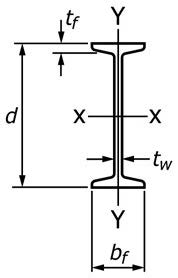
| Designation (Nominal Depth in Inches and Weight in Pounds per Linear Foot) | Area Ar in.2 | Depth dr in. | Flange | Web Thickness tw, in.A | Designation [Nominal Depth in Millimetres and Mass in Kilograms per Metre] | Area Ar mm2 | Depth dr mm | Flange | Web Thickness twA mm | ||
|---|---|---|---|---|---|---|---|---|---|---|---|
| Width bf in. | Thickness tf in.A | Width bf mm | Thickness tfA mm | ||||||||
| S 24 × 121 | 35.6 | 24.50 | 8.050 | 1.090 | 0.800 | S 610 × 180 | 23 000 | 622 | 204 | 27.7 | 20.3 |
| × 106 | 31.2 | 24.50 | 7.870 | 1.090 | 0.620 | × 158 | 20 100 | 622 | 200 | 27.7 | 15.7 |
| S 24 × 100 | 29.3 | 24.00 | 7.245 | 0.870 | 0.745 | S 610 × 149 | 18 900 | 610 | 184 | 22.1 | 18.9 |
| × 90 | 26.5 | 24.00 | 7.125 | 0.870 | 0.625 | × 134 | 17 100 | 610 | 181 | 22.1 | 15.9 |
| × 80 | 23.5 | 24.00 | 7.000 | 0.870 | 0.500 | × 119 | 15 200 | 610 | 178 | 22.1 | 12.7 |
| S 20 × 96 | 28.2 | 20.30 | 7.200 | 0.920 | 0.800 | S 510 × 143 | 18 200 | 516 | 183 | 23.4 | 20.3 |
| × 86 | 25.3 | 20.30 | 7.060 | 0.920 | 0.660 | × 128 | 16 300 | 516 | 179 | 23.4 | 16.8 |
| S 20 × 75 | 22.0 | 20.00 | 6.385 | 0.795 | 0.635 | S 510 × 112 | 14 200 | 508 | 162 | 20.2 | 16.1 |
| × 66 | 19.4 | 20.00 | 6.255 | 0.695 | 0.505 | × 98 | 12 500 | 508 | 159 | 20.2 | 12.8 |
| S 18 × 70 | 20.6 | 18.00 | 6.251 | 0.691 | 0.711 | S 460 × 104 | 13 300 | 457 | 159 | 17.6 | 18.1 |
| × 54.7 | 16.1 | 18.00 | 6.001 | 0.691 | 0.461 | × 81.4 | 10 400 | 457 | 152 | 17.6 | 11.7 |
| S 15 × 50 | 14.7 | 15.00 | 5.640 | 0.622 | 0.550 | S 380 × 74 | 9 480 | 381 | 143 | 15.8 | 14.0 |
| × 42.9 | 12.6 | 15.00 | 5.501 | 0.622 | 0.411 | × 64 | 8 130 | 381 | 140 | 15.8 | 10.4 |
| S 12 × 50 | 14.7 | 12.00 | 5.477 | 0.659 | 0.687 | S 310 × 74 | 9 480 | 305 | 139 | 16.7 | 17.4 |
| × 40.8 | 12.0 | 12.00 | 5.252 | 0.659 | 0.462 | × 60.7 | 7 740 | 305 | 133 | 16.7 | 11.7 |
| S 12 × 35 | 10.3 | 12.00 | 5.078 | 0.544 | 0.428 | S 310 × 52 | 6 650 | 305 | 129 | 13.8 | 10.9 |
| × 31.8 | 9.35 | 12.00 | 5.000 | 0.491 | 0.350 | × 47.3 | 6 030 | 305 | 127 | 13.8 | 8.9 |
| S 10 × 35 | 10.3 | 10.00 | 4.944 | 0.544 | 0.594 | S 250 × 52 | 6 650 | 254 | 126 | 12.5 | 15.1 |
| × 25.4 | 7.46 | 10.00 | 4.661 | 0.491 | 0.311 | × 37.8 | 4 810 | 254 | 118 | 12.5 | 7.9 |
| S 8 × 23 | 6.77 | 8.00 | 4.171 | 0.425 | 0.443 | S 200 × 34 | 4 370 | 203 | 106 | 10.8 | 11.2 |
| × 18.4 | 5.41 | 8.00 | 4.001 | 0.425 | 0.271 | × 27.4 | 3 480 | 203 | 102 | 10.8 | 6.9 |
| S 6 × 17.25 | 5.07 | 6.00 | 3.565 | 0.359 | 0.465 | S 150 × 25.7 | 3 270 | 152 | 91 | 9.1 | 11.8 |
| × 12.5 | 3.67 | 6.00 | 3.332 | 0.359 | 0.232 | × 18.6 | 2 360 | 152 | 85 | 9.1 | 5.9 |
| S 5 × 10 | 2.94 | 5.00 | 3.004 | 0.326 | 0.214 | S 130 × 15 | 1 880 | 127 | 76 | 8.3 | 5.4 |
| S 4 × 9.5 | 2.79 | 4.00 | 2.796 | 0.293 | 0.326 | S 100 × 14.1 | 1 800 | 102 | 71 | 7.4 | 8.3 |
| × 7.7 | 2.26 | 4.00 | 2.663 | 0.293 | 0.193 | × 11.5 | 1 450 | 102 | 68 | 7.4 | 4.9 |
| S 3 × 7.5 | 2.21 | 3.00 | 2.509 | 0.260 | 0.349 | S 75 × 11.2 | 1 430 | 76 | 64 | 6.6 | 8.9 |
| × 5.7 | 1.67 | 3.00 | 2.330 | 0.260 | 0.193 | × 8.5 | 1 080 | 76 | 59 | 6.6 | 4.3 |
AActual flange and web thicknesses vary due to mill rolling practices; however, permitted variations for such dimensions are not addressed.
TABLE A2.3 "M" Shapes
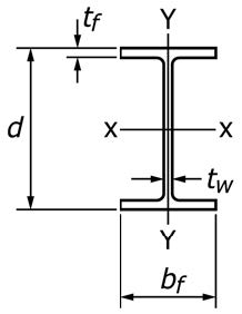
| Designation (Nominal Depth in Inches and Weight in Pounds per Linear Foot) | Area Ar in.2 | Depth dr in. | Flange | Web Thickness tw, in.A | Designation [Nominal Depth in Millimetres and Mass in Kilograms per Metre] | Area Ar mm2 | Depth dr mm | Flange | Web Thickness twA mm | ||
|---|---|---|---|---|---|---|---|---|---|---|---|
| Width bf in. | Thickness tf in.A | Width bf mm | Thickness tfA mm | ||||||||
| M 12.5 × 12.4 | 3.66 | 12.534 | 3.750 | 0.228 | 0.155 | M 318 × 18.5 | 2 361 | 318 | 95 | 5.8 | 3.9 |
| × 11.6 | 3.43 | 12.500 | 3.500 | 0.211 | 0.155 | × 17.3 | 2 213 | 317 | 89 | 5.4 | 3.9 |
| M 12 × 11.8 | 3.47 | 12.00 | 3.065 | 0.225 | 0.177 | M 310 × 17.6 | 2 240 | 305 | 78 | 5.7 | 4.5 |
| × 10.8 | 3.18 | 11.97 | 3.065 | 0.210 | 0.160 | × 16.1 | 2 050 | 304 | 78 | 5.3 | 4.1 |
| × 10.0 | 2.94 | 11.97 | 3.250 | 0.180 | 0.149 | × 14.9 | 1 900 | 304 | 83 | 4.6 | 3.8 |
| M 10 × 9.0 | 2.65 | 10.00 | 2.690 | 0.206 | 0.157 | M 250 × 13.4 | 1 710 | 254 | 68 | 4.6 | 3.6 |
| × 8.0 | 2.35 | 9.95 | 2.690 | 0.182 | 0.141 | × 11.9 | 1 520 | 253 | 68 | 5.2 | 4.0 |
| × 7.5 | 2.21 | 9.99 | 2.688 | 0.173 | 0.130 | × 11.2 | 1 430 | 253 | 68 | 4.4 | 3.3 |
| M 8 × 6.5 | 1.92 | 8.00 | 2.281 | 0.189 | 0.135 | M 200 × 9.7 | 1 240 | 203 | 57 | 4.8 | 3.4 |
| × 6.2 | 1.81 | 8.00 | 2.281 | 0.177 | 0.129 | × 9.2 | 1 170 | 203 | 58 | 4.5 | 3.3 |
| M 6 × 4.4 | 1.29 | 6.00 | 1.844 | 0.171 | 0.114 | M 150 × 6.6 | 832 | 152 | 47 | 4.3 | 2.9 |
| × 3.7 | 1.09 | 5.92 | 2.000 | 0.129 | 0.098 | × 5.5 | 703 | 150 | 51 | 3.3 | 2.5 |
| M 5 × 18.9 | 5.55 | 5.00 | 5.003 | 0.416 | 0.316 | M 130 × 28.1 | 3 580 | 127 | 127 | 10.6 | 8.0 |
| M 4 × 6.0 | 1.78 | 3.80 | 3.80 | 0.160 | 0.130 | M 100 × 8.9 | 1 150 | 97 | 97 | 4.1 | 3.3 |
| × 4.08 | 1.20 | 4.00 | 2.250 | 0.170 | 0.115 | × 6.1 | 775 | 102 | 57 | 4.3 | 2.9 |
| M 3 × 2.9 | 0.853 | 3.00 | 2.250 | 0.130 | 0.090 | M 75 × 4.3 | 550 | 76 | 57 | 3.3 | 2.3 |
AActual flange and web thicknesses vary due to mill rolling practices; however, permitted variations for such dimensions are not addressed.
TABLE A2.4 "HP" Shapes
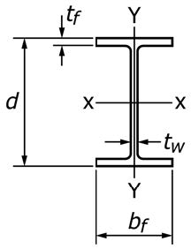
| Designation (Nominal Depth in Inches and Weight in Pounds per Linear Foot) | Area Ar in.2 | Depth dr in. | Flange | Web Thickness tw, in.A | Designation [Nominal Depth in Millimetres and Mass in Kilograms per Metre] | Area Ar mm2 | Depth dr mm | Flange | Web Thickness twA mm | ||
|---|---|---|---|---|---|---|---|---|---|---|---|
| Width bf in. | Thickness tf in.A | Width bf mm | Thickness tfA mm | ||||||||
| HP18 × 204 | 60.0 | 18.25 | 18.125 | 1.125 | 1.125 | HP460 × 304 | 38 700 | 464 | 460 | 28.6 | 28.6 |
| × 181 | 53.2 | 18.00 | 18.000 | 1.000 | 1.000 | × 269 | 34 300 | 457 | 457 | 25.4 | 25.4 |
| × 157 | 46.2 | 17.74 | 17.870 | 0.870 | 0.870 | × 234 | 29 800 | 451 | 454 | 22.1 | 22.1 |
| × 135 | 39.8 | 17.50 | 17.750 | 0.750 | 0.750 | × 202 | 25 700 | 445 | 451 | 19.1 | 19.1 |
| HP16 × 183 | 53.8 | 16.50 | 16.250 | 1.125 | 1.125 | HP410 × 272 | 34 700 | 419 | 413 | 28.6 | 28.6 |
| × 162 | 47.7 | 16.25 | 16.125 | 1.000 | 1.000 | × 242 | 30 800 | 413 | 410 | 25.4 | 25.4 |
| × 141 | 41.7 | 16.00 | 16.000 | 0.875 | 0.875 | × 211 | 26 900 | 406 | 406 | 22.2 | 22.2 |
| × 121 | 35.7 | 15.75 | 15.875 | 0.750 | 0.750 | × 181 | 23 000 | 400 | 403 | 19.1 | 19.1 |
| × 101 | 29.8 | 15.50 | 15.750 | 0.625 | 0.625 | × 151 | 19 200 | 394 | 399 | 15.9 | 15.9 |
| × 88 | 25.8 | 15.33 | 15.665 | 0.540 | 0.540 | × 131 | 16 700 | 389 | 398 | 13.7 | 13.7 |
| HP14 × 117 | 34.4 | 14.21 | 14.885 | 0.805 | 0.805 | HP360 × 174 | 22 200 | 361 | 378 | 20.4 | 20.4 |
| × 102 | 30.0 | 14.01 | 14.785 | 0.705 | 0.705 | × 152 | 19 400 | 356 | 376 | 17.9 | 17.9 |
| × 89 | 26.1 | 13.83 | 14.695 | 0.615 | 0.615 | × 132 | 16 800 | 351 | 373 | 15.6 | 15.6 |
| × 73 | 21.4 | 13.61 | 14.585 | 0.505 | 0.505 | × 108 | 13 800 | 346 | 370 | 12.8 | 12.8 |
| HP12 × 89 | 26.2 | 12.35 | 12.330 | 0.720 | 0.720 | HP310 × 132 | 16 900 | 314 | 313 | 18.3 | 18.3 |
| × 84 | 24.6 | 12.28 | 12.295 | 0.685 | 0.685 | × 125 | 15 900 | 312 | 312 | 17.4 | 17.4 |
| × 74 | 21.8 | 12.13 | 12.215 | 0.610 | 0.610 | × 110 | 14 100 | 308 | 310 | 15.5 | 15.4 |
| × 63 | 18.4 | 11.94 | 12.125 | 0.515 | 0.515 | × 93 | 11 900 | 303 | 308 | 13.1 | 13.1 |
| × 53 | 15.5 | 11.78 | 12.045 | 0.435 | 0.435 | × 79 | 10 000 | 299 | 306 | 11.0 | 11.0 |
| HP10 × 57 | 16.8 | 9.99 | 10.225 | 0.565 | 0.565 | HP250 × 85 | 10 800 | 254 | 260 | 14.4 | 14.4 |
| × 42 | 12.4 | 9.70 | 10.075 | 0.420 | 0.415 | × 62 | 8 000 | 246 | 256 | 10.7 | 10.5 |
| HP8 × 36 | 10.6 | 8.02 | 8.155 | 0.445 | 0.445 | HP200 × 53 | 6 840 | 204 | 207 | 11.3 | 11.3 |
AActual flange and web thicknesses vary due to mill rolling practices; however, permitted variations for such dimensions are not addressed.
TABLE A2.5 "C" Shapes

| Designation (Nominal Depth in Inches and Weight in Pounds per Linear Foot) |
Area Ar in.2 |
Depth dr in. |
Flange | Web Thick- ness tw in.A |
Designation [Nominal Depth in Millimetres and Mass in Kilograms per Metre] |
Area Ar mm2 |
Depth dr mm |
Flange | Web Thick- ness twA mm |
||
|---|---|---|---|---|---|---|---|---|---|---|---|
| Width bf in. |
Thick- ness tf in.A |
Width bf mm |
Thick- ness tfA mm |
||||||||
| C 15 × 50 | 14.7 | 15.00 | 3.716 | 0.650 | 0.716 | C 380 × 74 | 9 480 | 381 | 94 | 16.5 | 18.2 |
| × 40 | 11.8 | 15.00 | 3.520 | 0.650 | 0.520 | × 60 | 7 610 | 381 | 89 | 16.5 | 13.2 |
| × 33.9 | 9.96 | 15.00 | 3.400 | 0.650 | 0.400 | × 50.4 | 6 430 | 381 | 86 | 16.5 | 10.2 |
| C 12 × 30 | 8.82 | 12.00 | 3.170 | 0.501 | 0.500 | C 310 × 45 | 5 690 | 305 | 80 | 12.7 | 13.0 |
| × 25 | 7.35 | 12.00 | 3.047 | 0.501 | 0.387 | × 37 | 4 740 | 305 | 77 | 12.7 | 9.8 |
| × 20.7 | 6.09 | 12.00 | 2.942 | 0.501 | 0.282 | × 30.8 | 3 930 | 305 | 74 | 12.7 | 7.2 |
| C 10 × 30 | 8.82 | 10.00 | 3.033 | 0.436 | 0.673 | C 250 × 45 | 5 690 | 254 | 76 | 11.1 | 17.1 |
| × 25 | 7.35 | 10.00 | 3.003 | 0.436 | 0.526 | × 37 | 4 740 | 254 | 73 | 11.1 | 13.4 |
| × 20 | 5.88 | 10.00 | 2.739 | 0.436 | 0.379 | × 30 | 3 790 | 254 | 69 | 11.1 | 9.6 |
| × 15.3 | 4.49 | 10.00 | 2.600 | 0.436 | 0.240 | × 22.8 | 2 900 | 254 | 65 | 11.1 | 6.1 |
| C 9 × 20 | 5.88 | 9.00 | 2.648 | 0.413 | 0.448 | C 230 × 30 | 3 790 | 229 | 67 | 10.5 | 11.4 |
| × 15 | 4.41 | 9.00 | 2.485 | 0.413 | 0.285 | × 22 | 2 850 | 229 | 63 | 10.5 | 7.2 |
| × 13.4 | 3.94 | 9.00 | 2.433 | 0.390 | 0.233 | × 19.9 | 2 540 | 229 | 61 | 10.5 | 5.9 |
| C 8 × 18.75 | 5.51 | 8.00 | 2.527 | 0.439 | 0.487 | C 200 × 27.9 | 3 550 | 203 | 64 | 9.9 | 12.4 |
| × 13.75 | 4.04 | 8.00 | 2.343 | 0.390 | 0.303 | × 20.5 | 2 610 | 203 | 59 | 9.9 | 7.7 |
| × 11.5 | 3.38 | 8.00 | 2.260 | 0.390 | 0.220 | × 17.1 | 2 180 | 203 | 57 | 9.9 | 5.6 |
| C 7 × 14.75 | 4.33 | 7.00 | 2.299 | 0.366 | 0.419 | C 180 × 22 | 2 790 | 178 | 58 | 9.3 | 10.6 |
| × 12.25 | 3.60 | 7.00 | 2.194 | 0.366 | 0.314 | × 18.2 | 2 320 | 178 | 55 | 9.3 | 8.0 |
| × 9.8 | 2.87 | 7.00 | 2.090 | 0.366 | 0.210 | × 14.6 | 1 850 | 178 | 53 | 9.3 | 5.3 |
| C 6 × 13 | 3.83 | 6.00 | 2.157 | 0.343 | 0.437 | C 150 × 19.3 | 2 470 | 152 | 54 | 8.7 | 11.1 |
| × 10.5 | 3.09 | 6.00 | 2.034 | 0.343 | 0.314 | × 15.6 | 1 990 | 152 | 51 | 8.7 | 8.0 |
| × 8.2 | 2.40 | 6.00 | 1.920 | 0.343 | 0.200 | × 12.2 | 1 550 | 152 | 48 | 8.7 | 5.1 |
| C 5 × 9 | 2.64 | 5.00 | 1.885 | 0.320 | 0.325 | C 130 × 13 | 1 700 | 127 | 47 | 8.1 | 8.3 |
| × 6.7 | 1.97 | 5.00 | 1.750 | 0.320 | 0.190 | × 10.4 | 1 270 | 127 | 44 | 8.1 | 4.8 |
| C 4 × 7.25 | 2.13 | 4.00 | 1.721 | 0.296 | 0.321 | C 100 × 10.8 | 1 370 | 102 | 43 | 7.5 | 8.2 |
| × 6.25 | 1.84 | 4.00 | 1.647 | 0.296 | 0.247 | × 9.3 | 1 187 | 102 | 42 | 7.5 | 6.3 |
| × 5.4 | 1.59 | 4.00 | 1.584 | 0.296 | 0.184 | × 8 | 1 030 | 102 | 40 | 7.5 | 4.7 |
| × 4.5 | 1.32 | 4.00 | 1.520 | 0.296 | 0.125 | × 6.7 | 852 | 102 | 39 | 7.5 | 3.2 |
| C 3 × 6 | 1.76 | 3.00 | 1.596 | 0.356 | 0.347 | C 75 × 8.9 | 1 130 | 76 | 40 | 6.9 | 9.0 |
| × 5 | 1.47 | 3.00 | 1.498 | 0.273 | 0.258 | × 7.4 | 948 | 76 | 37 | 6.9 | 6.6 |
| × 4.1 | 1.21 | 3.00 | 1.410 | 0.273 | 0.170 | × 6.1 | 781 | 76 | 35 | 6.9 | 4.3 |
| × 3.5 | 1.03 | 3.00 | 1.372 | 0.273 | 0.132 | × 5.2 | 665 | 76 | 35 | 6.9 | 3.4 |
TABLE A2.6 "MC" Shapes
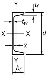
| Designation (Nominal Depth in Inches and Weight in Pounds per Linear Foot) |
Area Ar in.2 |
Depth dr in. |
Flange | Web Thick- ness tw in.A |
Designation [Nominal Depth in Millimetres and Mass in Kilograms per Metre] |
Area Ar mm2 |
Depth dr mm |
Flange | Web Thick- ness twA mm |
||
|---|---|---|---|---|---|---|---|---|---|---|---|
| Width bf in. |
Thick- ness tf in.A |
Width bf mm |
Thick- ness tfA mm |
||||||||
| MC 18 × 58 | 17.1 | 18.00 | 4.200 | 0.625 | 0.700 | MC 460 × 86 | 11 000 | 457 | 107 | 15.9 | 17.8 |
| × 51.9 | 15.3 | 18.00 | 4.100 | 0.625 | 0.600 | × 77.2 | 9 870 | 457 | 104 | 15.9 | 15.2 |
| × 45.8 | 13.5 | 18.00 | 4.000 | 0.625 | 0.500 | × 68.2 | 8 710 | 457 | 102 | 15.9 | 12.7 |
| × 42.7 | 12.6 | 18.00 | 3.950 | 0.625 | 0.450 | × 63.5 | 8 130 | 457 | 100 | 15.9 | 11.4 |
| MC 13 × 50 | 14.7 | 13.00 | 4.412 | 0.610 | 0.787 | MC 330 × 74 | 9 480 | 330 | 112 | 15.5 | 20.0 |
| × 40 | 11.8 | 13.00 | 4.185 | 0.610 | 0.566 | × 60 | 7 610 | 330 | 106 | 15.5 | 14.2 |
| × 35 | 10.3 | 13.00 | 4.072 | 0.610 | 0.447 | × 52 | 6 640 | 330 | 103 | 15.5 | 11.4 |
| × 31.8 | 9.35 | 13.00 | 4.000 | 0.610 | 0.375 | × 47.3 | 6 030 | 330 | 102 | 15.5 | 9.5 |
| MC 12 × 50 | 14.7 | 12.00 | 4.135 | 0.700 | 0.835 | MC 310 × 74 | 9 480 | 305 | 105 | 17.8 | 21.2 |
| × 45 | 13.2 | 12.00 | 4.010 | 0.700 | 0.710 | × 67 | 8 502 | 305 | 102 | 17.8 | 18.0 |
| × 40 | 11.8 | 12.00 | 3.890 | 0.700 | 0.590 | × 60 | 7 610 | 305 | 98 | 17.8 | 15.0 |
| × 35 | 10.3 | 12.00 | 3.765 | 0.700 | 0.465 | × 52 | 6 620 | 305 | 96 | 17.8 | 11.8 |
| × 31 | 9.12 | 12.00 | 3.670 | 0.700 | 0.370 | × 46 | 5 890 | 305 | 93 | 17.8 | 9.4 |
| MC 12 × 14.3 | 4.19 | 12.00 | 2.125 | 0.313 | 0.250 | MC 310 × 21.3 | 2 700 | 305 | 54 | 8.0 | 6.4 |
| × 10.6 | 3.10 | 12.00 | 2.000 | 0.309 | 0.190 | × 15.8 | 2 000 | 305 | 38 | 7.8 | 4.8 |
| MC 10 × 41.1 | 12.1 | 10.00 | 4.321 | 0.575 | 0.796 | MC 250 × 61.2 | 7 810 | 254 | 110 | 14.6 | 20.2 |
| × 33.6 | 9.87 | 10.00 | 4.100 | 0.575 | 0.575 | × 50 | 6 370 | 254 | 104 | 14.6 | 14.6 |
| × 28.5 | 8.37 | 10.00 | 3.950 | 0.575 | 0.425 | × 42.4 | 5 400 | 254 | 100 | 14.6 | 10.8 |
| MC 10 × 25 | 7.35 | 10.00 | 3.405 | 0.575 | 0.380 | MC 250 × 37 | 4 740 | 254 | 86 | 14.6 | 9.7 |
| × 22 | 6.45 | 10.00 | 3.315 | 0.575 | 0.290 | × 33 | 4 160 | 254 | 84 | 14.6 | 7.4 |
| MC 10 × 8.4 | 2.46 | 10.00 | 1.500 | 0.280 | 0.170 | MC 250 × 12.5 | 1 590 | 254 | 38 | 7.1 | 4.3 |
| × 6.5 | 1.91 | 10.00 | 1.17 | 0.202 | 0.152 | × 9.7 | 1 240 | 254 | 28 | 5.1 | 3.9 |
| MC 9 × 25.4 | 7.47 | 9.00 | 3.500 | 0.550 | 0.450 | MC 230 × 37.6 | 4 820 | 229 | 88 | 14.0 | 11.4 |
| × 23.9 | 7.02 | 9.00 | 3.450 | 0.550 | 0.400 | × 35.6 | 4 530 | 229 | 87 | 14.0 | 10.2 |
| MC 8 × 22.8 | 6.70 | 8.00 | 3.502 | 0.525 | 0.427 | MC 200 × 33.9 | 4 320 | 203 | 88 | 13.3 | 10.8 |
| × 21.4 | 6.28 | 8.00 | 3.450 | 0.525 | 0.375 | × 31.8 | 4 050 | 203 | 87 | 13.3 | 9.5 |
| MC 8 × 20 | 5.88 | 8.00 | 3.025 | 0.500 | 0.400 | MC 200 × 29.8 | 3 790 | 203 | 76 | 12.7 | 10.2 |
| × 18.7 | 5.50 | 8.00 | 2.978 | 0.500 | 0.353 | × 27.8 | 3 550 | 203 | 75 | 12.7 | 9.0 |
| MC 8 × 8.5 | 2.50 | 8.00 | 1.874 | 0.311 | 0.179 | MC 200 × 12.6 | 1 610 | 203 | 47 | 7.9 | 4.5 |
| MC 7 × 22.7 | 6.67 | 7.00 | 3.603 | 0.500 | 0.503 | MC 180 × 33.8 | 4 300 | 178 | 91 | 12.7 | 12.8 |
| × 19.1 | 5.61 | 7.00 | 3.452 | 0.500 | 0.352 | × 28.4 | 3 620 | 178 | 87 | 12.7 | 8.9 |
| MC 6 × 18 | 5.29 | 6.00 | 3.504 | 0.475 | 0.379 | MC 150 × 26.8 | 3 410 | 152 | 88 | 12.1 | 9.6 |
| × 15.3 | 4.50 | 6.00 | 3.500 | 0.385 | 0.340 | × 22.8 | 2 900 | 152 | 88 | 9.8 | 8.6 |
| MC 6 × 16.3 | 4.79 | 6.00 | 3.000 | 0.475 | 0.375 | MC 150 × 24.3 | 3 090 | 152 | 76 | 12.1 | 9.5 |
| × 15.1 | 4.44 | 6.00 | 2.941 | 0.475 | 0.316 | × 22.5 | 2 860 | 152 | 74 | 12.1 | 8.0 |
| MC 6 × 12 | 3.53 | 6.00 | 2.497 | 0.375 | 0.310 | MC 150 × 17.9 | 2 280 | 152 | 63 | 9.5 | 7.9 |
TABLE A2.6 Continued
| Designation (Nominal Depth in Inches and Weight in Pounds per Linear Foot) |
Area Ar in.2 |
Depth dr in. |
Flange | Web Thick- ness tw in.A |
Designation [Nominal Depth in Millimetres and Mass in Kilograms per Metre] |
Area Ar mm2 |
Depth dr mm |
Flange | Web Thick- ness twA mm |
||
|---|---|---|---|---|---|---|---|---|---|---|---|
| Width bf in. |
Thick- ness tf in.A |
Width bf mm |
Thick- ness tfA mm |
||||||||
| MC 6 × 7.0 | 2.07 | 6.00 | 1.875 | 0.291 | 0.179 | MC 150 × 10.4 | 1 341 | 152 | 48 | 7.4 | 4.5 |
| × 6.5 | 1.93 | 6.00 | 1.850 | 0.291 | 0.155 | × 9.7 | 1 250 | 152 | 47 | 7.4 | 3.9 |
| MC 4 × 13.8 | 4.09 | 4.00 | 2.500 | 0.500 | 0.500 | MC 100 × 20.5 | 2 594 | 102 | 64 | 13 | 13 |
| MC 3 × 7.1 | 2.09 | 3.00 | 1.938 | 0.351 | 0.312 | MC 75 × 10.6 | 1 348 | 76 | 49 | 8.9 | 7.9 |
TABLE A2.7 "L" Shapes (Equal Legs)A
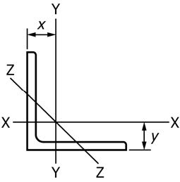
| Size and Thickness, in. | Weight per Foot, lb | Area, in.2 | Size and Thickness, mm | Mass per Metre, kg | Area, mm2 |
|---|---|---|---|---|---|
| L12 × 12 × 1⅜ | 105 | 30.9 | L305 × 305 × 34.9 | 157 | 19 900 |
| L12 × 12 × 1¼ | 96.4 | 28.3 | L305 × 305 × 31.8 | 143 | 18 300 |
| L12 × 12 × 1⅛ | 87.2 | 25.6 | L305 × 305 × 28.6 | 130 | 16 500 |
| L12 × 12 × 1 | 77.8 | 22.9 | L305 × 305 × 25.4 | 116 | 14 700 |
| L10 × 10 × 1⅜ | 87.1 | 25.6 | L254 × 254 × 34.9 | 130 | 16 500 |
| L10 × 10 × 1¼ | 79.9 | 23.5 | L254 × 254 × 31.8 | 119 | 15 100 |
| L10 × 10 × 1⅛ | 72.3 | 21.2 | L254 × 254 × 28.6 | 108 | 13 700 |
| L10 × 10 × 1 | 64.7 | 19.0 | L254 × 254 × 25.4 | 96.2 | 12 300 |
| L10 × 10 × ⅞ | 56.9 | 16.7 | L254 × 254 × 22.2 | 84.6 | 10 800 |
| L10 × 10 × ¾ | 49.1 | 14.4 | L254 × 254 × 19.1 | 73.1 | 9 310 |
| L8 × 8 × 1⅛ | 56.9 | 16.7 | L203 × 203 × 28.6 | 84.7 | 10 800 |
| L8 × 8 × 1 | 51.0 | 15.0 | L203 × 203 × 25.4 | 75.9 | 9 680 |
| L8 × 8 × ⅞ | 45.0 | 13.2 | L203 × 203 × 22.2 | 67.0 | 8 500 |
| L8 × 8 × ¾ | 38.9 | 11.4 | L203 × 203 × 19.0 | 57.9 | 7 360 |
| L8 × 8 × ⅝ | 32.7 | 9.61 | L203 × 203 × 15.9 | 48.7 | 6 200 |
| L8 × 8 × 9/16 | 29.6 | 8.68 | L203 × 203 × 14.3 | 44.0 | 5 600 |
| L8 × 8 × ½ | 26.4 | 7.75 | L203 × 203 × 12.7 | 39.3 | 5 000 |
| L6 × 6 × 1 | 37.4 | 11.0 | L152 × 152 × 25.4 | 55.7 | 7 100 |
| L6 × 6 × ⅞ | 33.1 | 9.73 | L152 × 152 × 22.2 | 49.3 | 6 280 |
| L6 × 6 × ¾ | 28.7 | 8.44 | L152 × 152 × 19.0 | 42.7 | 5 450 |
| L6 × 6 × ⅝ | 24.2 | 7.11 | L152 × 152 × 15.9 | 36.0 | 4 590 |
| L6 × 6 × 9/16 | 21.9 | 6.43 | L152 × 152 × 14.3 | 32.6 | 4 150 |
| L6 × 6 × ½ | 19.6 | 5.75 | L152 × 152 × 12.7 | 29.2 | 3 710 |
| L6 × 6 × 7/16 | 17.2 | 5.06 | L152 × 152 × 11.1 | 25.6 | 3 270 |
| L6 × 6 × ⅜ | 14.9 | 4.36 | L152 × 152 × 9.5 | 22.2 | 2 810 |
| L6 × 6 × 5/16 | 12.4 | 3.65 | L152 × 152 × 7.9 | 18.5 | 2 360 |
| L5 × 5 × ⅞ | 27.2 | 7.98 | L127 × 127 × 22.2 | 40.5 | 5 150 |
| L5 × 5 × ¾ | 23.6 | 6.94 | L127 × 127 × 19.0 | 35.1 | 4 480 |
| L5 × 5 × ⅝ | 20.0 | 5.86 | L127 × 127 × 15.9 | 29.8 | 3 780 |
| L5 × 5 × ½ | 16.2 | 4.75 | L127 × 127 × 12.7 | 24.1 | 3 070 |
| L5 × 5 × 7/16 | 14.3 | 4.18 | L127 × 127 × 11.1 | 21.3 | 2 700 |
| L5 × 5 × ⅜ | 12.3 | 3.61 | L127 × 127 × 9.5 | 18.3 | 2 330 |
| L5 × 5 × 5/16 | 10.3 | 3.03 | L127 × 127 × 7.9 | 15.3 | 1 960 |
| L4 × 4 × ¾ | 18.5 | 5.44 | L102 × 102 × 19.0 | 27.5 | 3 510 |
| L4 × 4 × ⅝ | 15.7 | 4.61 | L102 × 102 × 15.9 | 23.4 | 2 970 |
| L4 × 4 × ½ | 12.8 | 3.75 | L102 × 102 × 12.7 | 19.0 | 2 420 |
| L4 × 4 × 7/16 | 11.3 | 3.31 | L102 × 102 × 11.1 | 16.8 | 2 140 |
| L4 × 4 × ⅜ | 9.80 | 2.86 | L102 × 102 × 9.5 | 14.6 | 1 850 |
| L4 × 4 × 5/16 | 8.20 | 2.40 | L102 × 102 × 7.9 | 12.2 | 1 550 |
| L4 × 4 × ¼ | 6.60 | 1.94 | L102 × 102 × 6.4 | 9.8 | 1 250 |
| L3½ × 3½ × ½ | 11.1 | 3.25 | L89 × 89 × 12.7 | 16.5 | 2 100 |
| L3½ × 3½ × 7/16 | 9.80 | 2.87 | L89 × 89 × 11.1 | 14.6 | 1 850 |
| L3½ × 3½ × ⅜ | 8.50 | 2.48 | L89 × 89 × 9.5 | 12.6 | 1 600 |
| L3½ × 3½ × 5/16 | 7.20 | 2.09 | L89 × 89 × 7.9 | 10.7 | 1 350 |
| L3½ × 3½ × ¼ | 5.80 | 1.69 | L89 × 89 × 6.4 | 8.6 | 1 090 |
| L3 × 3 × ½ | 9.40 | 2.75 | L76 × 76 × 12.7 | 14.0 | 1 770 |
| L3 × 3 × 7/16 | 8.30 | 2.43 | L76 × 76 × 11.1 | 12.4 | 1 570 |
| L3 × 3 × ⅜ | 7.20 | 2.11 | L76 × 76 × 9.5 | 10.7 | 1 360 |
| L3 × 3 × 5/16 | 6.10 | 1.78 | L76 × 76 × 7.9 | 9.1 | 1 150 |
| L3 × 3 × ¼ | 4.90 | 1.44 | L76 × 76 × 6.4 | 7.3 | 929 |
| L3 × 3 × 3/16 | 3.71 | 1.09 | L76 × 76 × 4.8 | 5.5 | 703 |
TABLE A2.7 Continued
| Size and Thickness, in. | Weight per Foot, lb | Area, in.2 | Size and Thickness, mm | Mass per Metre, kg | Area, mm2 |
|---|---|---|---|---|---|
| L2½ × 2½ × ½ | 7.70 | 2.25 | L64 × 64 × 12.7 | 11.4 | 1 450 |
| L2½ × 2½ × ⅜ | 5.90 | 1.73 | L64 × 64 × 9.5 | 8.7 | 1 120 |
| L2½ × 2½ × 5/16 | 5.00 | 1.46 | L64 × 64 × 7.9 | 7.4 | 942 |
| L2½ × 2½ × ¼ | 4.10 | 1.19 | L64 × 64 × 6.4 | 6.1 | 768 |
| L2½ × 2½ × 3/16 | 3.07 | 0.90 | L64 × 64 × 4.8 | 4.6 | 581 |
| L2 × 2 × ⅜ | 4.70 | 1.36 | L51 × 51 × 9.5 | 7.0 | 877 |
| L2 × 2 × 5/16 | 3.92 | 1.15 | L51 × 51 × 7.9 | 5.8 | 742 |
| L2 × 2 × ¼ | 3.19 | 0.938 | L51 × 51 × 6.4 | 4.7 | 605 |
| L2 × 2 × 3/16 | 2.44 | 0.715 | L51 × 51 × 4.8 | 3.6 | 461 |
| L2 × 2 × ⅛ | 1.65 | 0.484 | L51 × 51 × 3.2 | 2.4 | 312 |
| L1¾ × 1¾ × ¼ | 2.77 | 0.813 | L44 × 44 × 6.4 | 4.1 | 525 |
| L1¾ × 1¾ × 3/16 | 2.12 | 0.621 | L44 × 44 × 4.8 | 3.1 | 401 |
| L1¾ × 1¾ × ⅛ | 1.44 | 0.422 | L44 × 44 × 3.2 | 2.1 | 272 |
| L1½ × 1½ × ¼ | 2.34 | 0.688 | L38 × 38 × 6.4 | 3.4 | 444 |
| L1½ × 1½ × 3/16 | 1.80 | 0.527 | L38 × 38 × 4.8 | 2.7 | 340 |
| L1½ × 1½ × 5/32 | 1.52 | 0.444 | L38 × 38 × 4.0 | 2.2 | 286 |
| L1½ × 1½ × ⅛ | 1.23 | 0.359 | L38 × 38 × 3.2 | 1.8 | 232 |
| L1¼ × 1¼ × ¼ | 1.92 | 0.563 | L32 × 32 × 6.4 | 2.8 | 363 |
| L1¼ × 1¼ × 3/16 | 1.48 | 0.434 | L32 × 32 × 4.8 | 2.2 | 280 |
| L1¼ × 1¼ × ⅛ | 1.01 | 0.297 | L32 × 32 × 3.2 | 1.5 | 192 |
| L1 × 1 × ¼ | 1.49 | 0.438 | L25 × 25 × 6.4 | 2.2 | 283 |
| L1 × 1 × 3/16 | 1.16 | 0.340 | L25 × 25 × 4.8 | 1.8 | 219 |
| L1 × 1 × ⅛ | 0.80 | 0.234 | L25 × 25 × 3.2 | 1.2 | 151 |
| L¾ × ¾ × ⅛ | 0.59 | 0.172 | L19 × 19 × 3.2 | 0.9 | 111 |
TABLE A2.8 "L" Shapes (Unequal Legs)
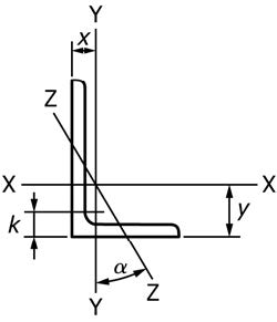
| Size and Thickness, in. | Weight per Foot, lb | Area, in.2 | Size and Thickness, mm | Mass per Metre, kg | Area, mm2 |
|---|---|---|---|---|---|
| L8 × 6 × 1 | 44.2 | 13.0 | L203 × 152 × 25.4 | 65.5 | 8 390 |
| L8 × 6 × ⅞ | 39.1 | 11.5 | L203 × 152 × 22.2 | 57.9 | 7 420 |
| L8 × 6 × ¾ | 33.8 | 9.94 | L203 × 152 × 19.0 | 50.1 | 6 410 |
| L8 × 6 × ⅝ | 28.5 | 8.36 | L203 × 152 × 15.9 | 42.2 | 5 390 |
| L8 × 6 × 9/16 | 25.7 | 7.56 | L203 × 152 × 14.3 | 38.1 | 4 880 |
| L8 × 6 × ½ | 23.0 | 6.75 | L203 × 152 × 12.7 | 34.1 | 4 350 |
| L8 × 6 × 7/16 | 20.2 | 5.93 | L203 × 152 × 11.1 | 29.9 | 3 830 |
| L8 × 4 × 1 | 37.4 | 11.0 | L203 × 102 × 25.4 | 55.4 | 7 100 |
| L8 × 4 × ⅞ | 33.1 | 9.73 | L203 × 102 × 22.2 | 49.3 | 6 280 |
| L8 × 4 × ¾ | 28.7 | 8.44 | L203 × 102 × 19.0 | 42.5 | 5 450 |
| L8 × 4 × ⅝ | 24.2 | 7.11 | L203 × 102 × 15.9 | 36.0 | 4 590 |
| L8 × 4 × 9/16 | 21.9 | 6.43 | L203 × 102 × 14.3 | 32.4 | 4 150 |
| L8 × 4 × ½ | 19.6 | 5.75 | L203 × 102 × 12.7 | 29.0 | 3 710 |
| L8 × 4 × 7/16 | 17.2 | 5.06 | L203 × 102 × 11.1 | 25.6 | 3 260 |
| L7 × 4 × ¾ | 26.2 | 7.69 | L178 × 102 × 19.0 | 38.8 | 4 960 |
| L7 × 4 × ⅝ | 22.1 | 6.48 | L178 × 102 × 15.9 | 32.7 | 4 180 |
| L7 × 4 × ½ | 17.9 | 5.25 | L178 × 102 × 12.7 | 26.5 | 3 390 |
| L7 × 4 × 7/16 | 15.7 | 4.62 | L178 × 102 × 11.1 | 23.4 | 2 980 |
| L7 × 4 × ¼ | 13.6 | 3.98 | L178 × 102 × 9.5 | 20.2 | 2 570 |
| L6 × 4 × ⅞ | 27.2 | 7.98 | L152 × 102 × 22.2 | 40.3 | 5 150 |
| L6 × 4 × ¾ | 23.6 | 6.94 | L152 × 102 × 19.0 | 35.0 | 4 480 |
| L6 × 4 × ⅝ | 20.0 | 5.86 | L152 × 102 × 15.9 | 29.6 | 3 780 |
| L6 × 4 × 9/16 | 18.1 | 5.31 | L152 × 102 × 14.3 | 26.8 | 3 430 |
| L6 × 4 × ½ | 16.2 | 4.75 | L152 × 102 × 12.7 | 24.0 | 3 060 |
| L6 × 4 × 7/16 | 14.3 | 4.18 | L152 × 102 × 11.1 | 21.2 | 2 700 |
| L6 × 4 × ⅜ | 12.3 | 3.61 | L152 × 102 × 9.5 | 18.2 | 2 330 |
| L6 × 4 × 5/16 | 10.3 | 3.03 | L152 × 102 × 7.9 | 15.3 | 1 950 |
| L6 × 3½ × ½ | 15.3 | 4.50 | L152 × 89 × 12.7 | 22.7 | 2 900 |
| L6 × 3½ × 7/16 | 11.7 | 3.42 | L152 × 89 × 9.5 | 17.3 | 2 210 |
| L6 × 3½ × 9/16 | 9.80 | 2.87 | L152 × 89 × 7.9 | 14.5 | 1 850 |
| L5 × 3½ × ¾ | 19.8 | 5.81 | L127 × 89 × 19.0 | 29.3 | 3 750 |
| L5 × 3½ × ⅝ | 16.8 | 4.92 | L127 × 89 × 15.9 | 24.9 | 3 170 |
| L5 × 3½ × ½ | 13.6 | 4.00 | L127 × 89 × 12.7 | 20.2 | 2 580 |
| L5 × 3½ × 7/16 | 10.4 | 3.05 | L127 × 89 × 9.5 | 15.4 | 1 970 |
| L5 × 3½ × ⅜ | 8.70 | 2.56 | L127 × 89 × 7.9 | 12.9 | 1 650 |
| L5 × 3½ × ¼ | 7.00 | 2.06 | L127 × 89 × 6.4 | 10.4 | 1 330 |
| L5 × 3 × ½ | 12.8 | 3.75 | L127 × 76 × 12.7 | 19.0 | 2 420 |
| L5 × 3 × 7/16 | 11.3 | 3.31 | L127 × 76 × 11.1 | 16.7 | 2 140 |
| L5 × 3 × ⅜ | 9.80 | 2.86 | L127 × 76 × 9.5 | 14.5 | 1 850 |
| L5 × 3 × 5/16 | 8.20 | 2.40 | L127 × 76 × 7.9 | 12.1 | 1 550 |
| L5 × 3 × ¼ | 6.60 | 1.94 | L127 × 76 × 6.4 | 9.8 | 1 250 |
| L4 × 3½ × ½ | 11.9 | 3.50 | L102 × 89 × 12.7 | 17.6 | 2 260 |
| L4 × 3½ × 7/16 | 9.10 | 2.67 | L102 × 89 × 9.5 | 13.5 | 1 720 |
| L4 × 3½ × ⅜ | 7.70 | 2.25 | L102 × 89 × 7.9 | 11.4 | 1 450 |
| L4 × 3½ × ¼ | 6.20 | 1.81 | L102 × 89 × 6.4 | 9.2 | 1 170 |
TABLE A2.8 Continued
| Size and Thickness, in. | Weight per Foot, lb | Area, in.2 | Size and Thickness, mm | Mass per Metre, kg | Area, mm2 |
|---|---|---|---|---|---|
| L4 × 3 × ⅝ | 13.6 | 3.98 | L102 × 76 × 15.9 | 20.2 | 2 570 |
| L4 × 3 × ½ | 11.1 | 3.25 | L102 × 76 × 12.7 | 16.4 | 2 100 |
| L4 × 3 × ⅜ | 8.50 | 2.48 | L102 × 76 × 9.5 | 12.6 | 1 600 |
| L4 × 3 × 5/16 | 7.20 | 2.09 | L102 × 76 × 7.9 | 10.7 | 1 350 |
| L4 × 3 × ¼ | 5.80 | 1.69 | L102 × 76 × 6.4 | 8.6 | 1 090 |
| L3½ × 3 × ½ | 10.2 | 3.00 | L89 × 76 × 12.7 | 15.1 | 1 940 |
| L3½ × 3 × 7/16 | 9.10 | 2.65 | L89 × 76 × 11.1 | 13.5 | 1 710 |
| L3½ × 3 × ⅜ | 7.90 | 2.30 | L89 × 76 × 9.5 | 11.7 | 1 480 |
| L3½ × 3 × 5/16 | 6.60 | 1.93 | L89 × 76 × 7.9 | 9.8 | 1 250 |
| L3½ × 3 × ¼ | 5.40 | 1.56 | L89 × 76 × 6.4 | 8.0 | 1 010 |
| L3½ × 2½ × ½ | 9.40 | 2.75 | L89 × 64 × 12.7 | 13.9 | 1 770 |
| L3½ × 2½ × ⅜ | 7.20 | 2.11 | L89 × 64 × 9.5 | 10.7 | 1 360 |
| L3½ × 2½ × 5/16 | 6.10 | 1.78 | L89 × 64 × 7.9 | 9.0 | 1 150 |
| L3½ × 2½ × ¼ | 4.90 | 1.44 | L89 × 64 × 6.4 | 7.3 | 929 |
| L3 × 2½ × ½ | 8.50 | 2.50 | L76 × 64 × 12.7 | 12.6 | 1 610 |
| L3 × 2½ × 7/16 | 7.60 | 2.21 | L76 × 64 × 11.1 | 11.3 | 1 430 |
| L3 × 2½ × ⅜ | 6.60 | 1.92 | L76 × 64 × 9.5 | 9.8 | 1 240 |
| L3 × 2½ × 5/16 | 5.60 | 1.62 | L76 × 64 × 7.9 | 8.3 | 1 050 |
| L3 × 2½ × ¼ | 4.50 | 1.31 | L76 × 64 × 6.4 | 6.7 | 845 |
| L3 × 2½ × 3/16 | 3.39 | 0.996 | L76 × 64 × 4.8 | 5.1 | 643 |
| L3 × 2 × ½ | 7.70 | 2.25 | L76 × 51 × 12.7 | 11.5 | 1 450 |
| L3 × 2 × ⅜ | 5.90 | 1.73 | L76 × 51 × 9.5 | 8.8 | 1 120 |
| L3 × 2 × 5/16 | 5.00 | 1.46 | L76 × 51 × 7.9 | 7.4 | 942 |
| L3 × 2 × ¼ | 4.10 | 1.19 | L76 × 51 × 6.4 | 6.1 | 768 |
| L3 × 2 × 3/16 | 3.07 | 0.902 | L76 × 51 × 4.8 | 4.6 | 582 |
| L2½ × 2 × ⅜ | 5.30 | 1.55 | L64 × 51 × 9.5 | 7.9 | 1 000 |
| L2½ × 2 × 5/16 | 4.50 | 1.31 | L64 × 51 × 7.9 | 6.7 | 845 |
| L2½ × 2 × ¼ | 3.62 | 1.06 | L64 × 51 × 6.4 | 5.4 | 684 |
| L2½ × 2 × 3/16 | 2.75 | 0.809 | L64 × 51 × 4.8 | 4.2 | 522 |
| L2½ × 1½ × ¼ | 3.19 | 0.938 | L64 × 38 × 6.4 | 4.8 | 605 |
| L2½ × 1½ × 3/16 | 2.44 | 0.715 | L64 × 38 × 4.8 | 3.6 | 461 |
| L2 × 1½ × ¼ | 2.77 | 0.813 | L51 × 38 × 6.4 | 4.2 | 525 |
| L2 × 1½ × 3/16 | 2.12 | 0.621 | L51 × 38 × 4.8 | 3.1 | 401 |
| L2 × 1½ × ⅛ | 1.44 | 0.422 | L51 × 38 × 3.2 | 2.1 | 272 |
APPENDIXES
(Nonmandatory Information)
X1. COIL AS A SOURCE OF STRUCTURAL PRODUCTS
X1.1 Continuous wide hot strip rolling mills are normally equipped with coilers. Regardless of the different types of systems employed during or following the rolling operations, it is common for the steel to be reeled into the coiler at temperatures in the stress-relieving range. In general, such temperatures are higher as the steel thickness increases. The coils subsequently cool to ambient temperature with outer and inner laps cooling more rapidly than central laps. The difference in cooling rate can result in measurable differences in the mechanical properties throughout a coil. Data confirm reduced yield and tensile strength with increased percent elongation for the steel with slower cooling rates from the coiling temperature to ambient. Such differences are in addition to the effects on mechanical properties caused by differences in heat analysis and chemical segregation.
X2. VARIATION OF TENSILE PROPERTIES IN PLATES AND SHAPES
X2.1 The tension testing requirements of this specification are intended only to characterize the tensile properties of a heat of steel for determination of conformance to the requirements of the applicable product specification. Such testing procedures are not intended to define the upper or lower limits of tensile properties at all possible test locations within a heat of steel. It is well known and documented that tensile properties will vary within a heat or individual piece of steel as a function of chemical composition, processing, testing procedure and other factors. It is, therefore, incumbent on designers and engineers to use sound engineering judgement when using tension test results shown on mill test reports. The testing procedures of this specification have been found to provide structural products adequate for normal structural design criteria.
X2.2 A survey of the variation to be expected in tensile properties obtained from plates and structural shapes was conducted by the American Iron and Steel Institute (AISI). The results of this survey are contained in a Contribution to the Metallurgy of Steel entitled "The Variation of Product Analysis and Tensile Properties—Carbon Steel Plates and Wide Flange Shapes" (SU/18, SU/19 and SU/20), published in September 1974. The data are presented in tables of probability that tensile properties at other than the official location may differ from those of the reported test location. Another survey sponsored by the AISI entitled "Statistical Analysis of Structural Plate Mechanical Properties" was published in January 2003. That survey analyzed the results of variability testing on more modern as-rolled steels that were generally of higher minimum yield strength steels and also compared those results statistically to the previous surveys.
X2.3 This specification contains no requirements applicable to product tension tests; conformance to the applicable product specification is determined on the basis of tests performed at the place of manufacture or processing prior to shipment, unless otherwise specified.
X2.4 A task group of ASTM Subcommittee A01.02 has determined, based on review of the earlier AISI data, that the variation in tensile properties of plates and structural shapes can be expressed as a function of specified requirements: one standard deviation equals approximately 4 % of required tensile strength, 8 % of required yield strength, and 3 percentage points of required elongation. The January 2003 survey resulted in similar findings.
X2.5 Acceptance criteria for product testing based upon these values, either below the minimum or above the maximum allowed by the applicable product specification, are generally acceptable to manufacturers. Such tolerances could be considered by users of structural products as a reasonable basis for acceptance of structural products that, due to their inherent variability, deviate from the applicable product specification requirements when subjected to product tension testing.
X3. WELDABILITY OF STEEL
X3.1 Weldability is a term that usually refers to the relative ease with which a metal can be welded using conventional practice. Difficulties arise in steel when the cooling rates associated with weld thermal cycles produce microstructures (for example, martensite) that are susceptible to brittle fracture or, more commonly, hydrogen-induced (or cold) cracking. (Solidification or hot cracking is a relatively rare phenomenon that will not be addressed here. See Randall for further information.)
X3.2 The relative sensitivity of steels to forming cold cracking microstructures is called hardenability and can be measured in a number of ways. Perhaps the most popular method of assessing this is by the carbon equivalent (CE) formula, which attempts to equate the relative hardening contributions of a steel's constituent elements (for example, manganese, vanadium) to an equivalent amount of carbon, which is the most significant hardening agent. The most popular formula is the International Institute of Welding (IIW) equation presented in S31.2, which has been found suitable for predicting hardenability in a wide range of commonly used carbon-manganese and low alloy steels.
X3.3 It should be noted, however, that for the current generation of low carbon (<0.10 %) low alloy steels that derive strength from a combination of microalloying and thermal processing methods the use of other formulae may more accurately assess hardenability and cold cracking sensitivity.
X3.4 For a vast number of common structural applications it is unnecessary to specify the use of CE limits. However, in order to obtain a higher level of confidence in avoiding cold cracking, the chemistry controls in S31 are available. A purchaser who specifies the use of S31 should be aware that there are several factors involved in the judicious selection of a maximum CE value, such as the following:
- X3.4.1 Actual production joint restraint/base metal thickness(es),
- X3.4.2 Filler metal and base metal strength compatibility,
- X3.4.3 Deposited weld metal diffusible hydrogen content,
- X3.4.4 Preheat and interpass temperatures,
- X3.4.5 Filler metal and base metal cleanliness, and
- X3.4.6 Heat input.
X3.5 Though it is widely believed that low CE steels are immune to weld cracking problems, failure to consider these factors and others have resulted in weld or base metal HAZ (heat affected zone) cracks in such steels.11
X3.6 It is important to note that carbon equivalence is only a qualitative assessment of potential welding problems, and should never be solely relied on to ensure weld integrity. The proper use of welding specifications, coupled with the knowledge of actual construction conditions, must also be used.
X4. RADIUS FOR COLD BENDING
X4.1 Suggested minimum inside bend radii for cold forming are referenced to Group Designations A to F inclusive as defined in Table X4.1. The suggested radii listed in Table X4.2 should be used as minimums in typical shop fabrication. Material that does not form satisfactorily when fabricated in accordance with Table X4.2 may be subject to rejection pending negotiation with the steel supplier. When tighter bends are required, the manufacturer should be consulted.
X4.2 The bend radius and the radius of the male die should be as liberal as the finished part will permit. The width across the shoulders of the female die should be at least eight times the plate thickness. Higher strength steels require larger die openings. The surface of the dies in the area of radius should be smooth.
X4.2.1 Since cracks in cold bending commonly originate from the outside edges, shear burrs and gas cut edges should be removed by grinding. Sharp corners on edges and on punched or gas cut holes should be removed by chamfering or grinding to a radius.
X4.2.2 If possible, parts should be formed such that the bend line is perpendicular to the direction of final rolling. If it is necessary to bend with the bend line parallel to the direction of final rolling, a more generous radius is suggested (1½ times applicable value given in Table X4.2 for bend lines perpendicular to the direction of rolling).
TABLE X4.1 Group Designations for Cold Bending
| Specification | Grade | Group DesignationA |
|---|---|---|
| A36/A36M | B | B |
| A131/A131M | A, B, D, CS and E | B |
| A, B, D, CS and E (all cold flanging) | B | |
| AH32, DH32, EH32 and FH32 | C | |
| AH36, DH36, EH36 and FH36 | C | |
| AH40, DH40, EH40 and FH40 | C | |
| A242/A242M | B | C |
| A283/A283M | A or B | A |
| C or D | B | |
| A514/A514M | any | F |
| A529/A529M | 50 [345] or 55 [380] | C |
| A572/A572M | 42 [290] | B |
| 50 [345] | C | |
| 55 [380] | D | |
| 60 [415] or 65 [450] | E | |
| A573/A573M | 58 [400] or 65 [450] | B |
| 70 [485] | C | |
| A588/A588M | any | C |
| A633/A633M | any | B |
| A656/A656M | 50 [345] | B |
| 60 [415] | D | |
| 70 [485] | E | |
| 80 [550] or 100 [690] | F | |
| A678/A678M | A or B | C |
| C or D | D | |
| A709/A709M | 36 [250] | B |
| 50 [345], 50W [345W] or HPS 50W [HPS 345W] | C | |
| HPS 70W [HPS 485W] | D | |
| HPS 100W [HPS 690W] | F | |
| A710/A710M | A | F |
| A808/A808M | B | C |
| A852/A852M | B | D |
| A871/A871M | 60 [415] or 65 [450] | E |
| A945/A945M | 50 [345] or 65 [450] | B |
B Grade designations are not applicable for this specification.
TABLE X4.2 Suggested Minimum Inside Radii for Cold BendingA
| Group DesignationB | Thickness (t), in. [mm] | |||
|---|---|---|---|---|
| Up to ¾ in. [20 mm] | Over ¾ in. [20 mm] To 1 [25 mm, incl] | Over 1 in. [25 mm] To 2 in. [50 mm, incl] | Over 2 in. [50 mm] | |
| A | 1.5t | 1.5t | 1.5t | 1.5t |
| B | 1.5t | 1.5t | 1.5t | 2.0t |
| C | 1.5t | 1.5t | 2.0t | 2.5t |
| D | 1.5t | 1.5t | 2.5t | 3.0t |
| E | 1.5t | 1.5t | 3.0t | 3.5t |
| F | 1.75t | 2.25t | 4.5t | 5.5t |
B Steel specifications included in the group designations may not include the entire thickness range shown in this table.
X4.3 References
X4.3.1 Holt, G.E., et al., "Minimum Cold Bend Radii Project—Final Report," Concurrent Technologies Corporation, January 27, 1997.
X4.3.2 Brockenbrough, R.L., "Fabrication Guidelines for Cold Bending," R.L. Brockenbrough & Associates, June 28, 1998.
微信客服
专业客服在线解答

APP下载
随时随地查询现货