Structural steel—Hot-rolled plates, floorplates and slabs
(Incorporating Amendment No. 1, December 2017)
Originated in Australia as part of AS A1‑1925.
Originated in New Zealand as AS/NZS 3678:1996.
Previous edition 2011.
Fourth edition 2016.
Reissued incorporating Amendment No. 1 (December 2017).
PREFACE
This Standard was prepared by the Joint Standards Australia/Standards New Zealand Committee BD‑023, Structural Steel, to supersede AS/NZS 3678:2011.
This Standard incorporates Amendment No. 1 (December 2017). The changes required by the Amendment are indicated in the text by a marginal bar and amendment number against the clause, note, table, figure or part thereof affected.
The objective of this Standard is to specify requirements for manufacturers and suppliers of hot‑rolled plates, floorplates and slabs for general structural and engineering applications.
This edition includes the following major changes from the previous edition.
- (a) Requirements for type testing and minimum production testing and inspections have been included in the normative appendix on product conformity.
- (b) Test certificates are required to be available for all products produced to this Standard.
- (c) Labelling requirements have been added to enable products compliant with this Standard to be traceable back to their corresponding test certificate.
- (d) Definitions, clause numbering and layout across the four steel‑product Standards AS/NZS 1163, AS/NZS 3678, AS/NZS 3679.1 and AS/NZS 3679.2 are consistent, wherever practicable.
- (e) Additional definitions in Clause 3.
- (g) Notation clause removed as duplicated in document. All notation defined in line.
- (h) Sulfur limits for some Z grades.
- (i) Internal soundness clause added.
- (j) Tensile test dimensions defined.
- (k) Through thickness tested grades down to 12 mm thickness.
- (l) Mechanically tested grades up to 200 mm thickness.
- (m) LO impact tested grades have been reintroduced.
- (n) 'None' impact designation has been removed.
- (o) Option for zinc coating classification referring to AS/NZS 2312.2, Clause 9.1.
A statement expressed in mandatory terms in a note to a table is deemed to be a requirement of this Standard.
The terms 'normative' and 'informative' have been used in this Standard to define the application of the appendix to which they apply. A 'normative' appendix is an integral part of a Standard, whereas an 'informative' appendix is only for information and guidance.
Contents
1 SCOPE. 4
2 NORMATIVE REFERENCES 4
3 DEFINITIONS. 5
4 DESIGNATION. 8
5 MANUFACTURING PROCESS. 9
6 CHEMICAL COMPOSITION. 10
7 MANUFACTURING TOLERANCES. 13
8 FREEDOM FROM DEFECTS. 13
9 TESTING. 16
10 MECHANICAL PROPERTIES. 19
11 IDENTIFICATION, TEST AND INSPECTION CERTIFICATES. 22
12 SAMPLING AND TESTING TO DEMONSTRATE PRODUCT CONFORMITY. 24
13 ROUNDING OF NUMBERS. 24
14 MANIPULATION. 25

APPENDICES
A PURCHASING GUIDELINES. 26
B PRODUCT CONFORMITY. 28
C COLD‑BENDING AND HOT‑FORMING OF PLATE DURING FABRICATION. 33
D NOT USED. 34
E NOT USED. 35
F STEEL FOR SEISMIC AND FRACTURE CRITICAL APPLICATIONS (NEW ZEALAND ONLY). 36

BIBLIOGRAPHY. 38
1 SCOPE
This Standard specifies requirements for the production and supply of hot‑rolled structural steel plates and floorplates for mechanically‑tested steels, analysis‑only steels, and mechanically‑tested weathering steels. This Standard also specifies requirements for the production and supply of wide slabs as fully‑killed analysis‑only steel.
This Standard is intended for general structural and engineering applications. All grades specified in this Standard are suitable for—
- (a) welding in accordance with AS/NZS 1554, Parts 1, 2, 5 and 7; and
- (b) fastening as specified in AS 3990, AS 4100, AS/NZS 4600, AS 5100.6 and NZS 3404.1.
This Standard does not cover the following:
- (i) Steel plates for pressure equipment.
- (ii) Hot‑rolled steel flat products.
- (iii) Quenched and tempered plate – structural and pressure vessel steel.
Requirements for product conformity to this Standard are given in Appendix B.
NOTES:
- Guidelines to purchasers on requirements that should be specified by the purchaser and those that should or may be agreed on at the time of enquiry and order are given in Appendix A.
- Guidelines on cold‑bending and hot‑forming of plate during fabrication are given in Appendix C.
2 NORMATIVE REFERENCES
The following normative documents are referenced in this Standard.
NOTE: Documents referenced for informative purposes are listed in the Bibliography.
- AS 1391 Metallic materials—Tensile testing at ambient temperature
- AS 1544 Methods for impact tests on metals
- AS 1544.2 Part 2: Charpy V‑notch
- AS 1733 Methods for the determination of grain size in metals
- AS 2706 Numerical values—Rounding and interpretation of limiting values
- AS 3990 Mechanical equipment—Steelwork
- AS 4100 Steel structures
- AS 5100 Bridge design
- AS 5100.6 Part 6: Steel and composite construction
- AS/NZS 1050 Methods for the analysis of iron and steel (series)
- AS/NZS 1050.1 Part 1: Sampling iron and steel for chemical analysis
- AS/NZS 1365 Tolerances for flat‑rolled steel products
- AS/NZS 1554.1 Part 1: Welding of steel structures
- AS/NZS 1554.2 Part 2: Stud welding (steel studs to steel)
- AS/NZS 1554.5 Part 5: Welding of steel structures subject to high levels of fatigue loading
- AS/NZS 1554.7 Part 7: Welding of sheet steel structures
- AS/NZS 4600 Cold‑formed steel structures
- ISO 404 Steel and steel products—General technical delivery requirements
- ISO 2566 Steel—Conversion of elongation values
- ISO 2566‑1 Part 1: Carbon and low alloy steels
- ISO 14284 Steel and iron—Sampling and preparation of samples for the determination of chemical composition
- NZS 3404 Steel Structures Standard
- NZS 3404.1 Part 1: Materials, fabrication and construction
- SAE 1403 Chemical compositions of SAE carbon steels
3 DEFINITIONS
For the purpose of this Standard, the definitions below apply.
3.1 Analysis
3.1.1 Cast analysis
Chemical analysis determined from test samples taken from the ladle, tundish or mould during casting.
3.1.2 Product analysis
Chemical analysis determined from a test sample of the finished product.
3.2 Batch
A group of rolled parent plates consisting of finished steel of the same yield stress gradation (see Table 7) and product form, treated in the same manner and from the same heat.
3.3 Can
To denote a capability or possibility that is available or that might occur.
3.4 Crack
Narrow line of fracture on the surface.
3.5 Defects
Surface discontinuity, including cracks, laps and seams, with a depth or area, or both, greater than a specified limiting value.
3.6 Edge conditions
3.6.1 Trimmed edge
Edge produced by the removal of material by mechanical means or gas cutting, also referred to as sheared, slit or thermal‑cut edge.
3.6.2 Untrimmed edge
Edge produced by the rolling between horizontal rolls, with or without vertical edging rolls, also referred to as mill, universal or rolled edge.
3.7 Factory production control
Operational techniques and all measures necessary to regulate and maintain the conformity of the product to the requirements of the relevant product standard.
3.8 Fine grained steels
Steels which have an austenitic grain size of number 6 or finer when tested in accordance with AS 1733. Generally, steels are considered fine grained without the need for testing when the total aluminium content is greater than 0.020% or when niobium ≥ 0.01% titanium ≥ 0.01% or vanadium ≥ 0.02% are deliberately added as carbonitride formers.
NOTE: AS 1733 includes various recognized methods for grain size determination, including the McQuaid‑Ehn method, and appropriate etching techniques.
3.9 Floorplate
Hot‑rolled product supplied flat, having a rolled raised pattern at regular intervals on one surface, with width greater than or equal to 900 mm, with a nominal thickness greater than or equal to 4.50 mm. Edges are either trimmed or untrimmed.
3.10 Heat
A product of a ladle of steel melted in one vessel and processed under the same conditions.
3.11 Imperfection
Surface discontinuities, other than cracks, lap and seams, with a depth or area or both less than or equal to a specified limiting value.
3.12 Inspection
Judgement by competent personnel to determine acceptability against requirements.
3.13 Lap
Overlapping material partially connected with the base material.
3.14 Longitudinal direction
Direction of the greatest extension of the steel during rolling (X direction).
3.15 Manufacturer
The business operating the hot rolling process producing the finished steel product.
3.16 May
Indicates the existence of an option.
3.17 Normalized
Steel produced by heating to a suitable temperature above the transformation range (typically 870°C to 930°C) and then cooling in still air to a temperature substantially below the transformation range.
3.18 Parent plate
Designates the whole of the plate which has the same thickness and heat treatment (if any) as that of the finished product, obtained from one slab. (Also known as 'rolled plate' or 'mother plate').
3.19 Plate
Hot‑rolled product supplied flat, with a width greater than or equal to 900 mm with nominal thickness greater than or equal to 4.50 mm. Edges are either trimmed or untrimmed.
3.20 Purchaser
Organization or person who is a recipient from a supplier of a steel product manufactured to this Standard.
3.21 Seams
Caused when defects in the semi‑finished product are elongated and extended during rolling.
3.22 Shall
Indicates that a statement is mandatory.
3.23 Should
Indicates a recommendation.
3.24 Slab
A semi‑finished rolled or continuously‑cast product with a rectangular cross‑section, with thickness greater than 100 mm and a width‑to‑thickness ratio of not less than 4:1.
3.25 Supplier
An organization or person that provides steel products manufactured to this Standard.
3.26 Testing
Chemical analysis tests and mechanical tests undertaken by an accredited laboratory as required by this Standard.
3.27 Test piece
Piece prepared for testing, made from a test specimen by a mechanical operation.
3.28 Test sample
Portion of material or product, or a group of items selected from a test batch or group by a sampling procedure.
3.29 Test specimen
Portion or a single item taken from the test sample for the purpose of eventually applying a particular test.
3.30 Through‑thickness direction
Direction perpendicular to the plate surface (Z direction).
3.31 Transverse direction
Direction at right angles to the direction of the greatest extension of the steel during rolling (Y direction).
3.32 Type testing
Testing performed to prove that the material is capable of conforming to the requirements of this Standard.
4 DESIGNATION
4.1 General
All grades shall be designated in accordance with the procedures specified in Clause 4.2 or Clause 4.4, as applicable. Additional modifications may be designated with the procedures specified in Clause 4.3, Clause 4.5 or Clause 4.6, as applicable. All designations shall include the number of this Australian/New Zealand Standard, i.e. AS/NZS 3678.
Grades designated with a WR prefix, offer enhanced atmospheric corrosion resistance over unalloyed grades.
4.2 Mechanically tested grades
Mechanically tested carbon and carbon‑manganese grades and low alloy (weathering) grades shall be designated as follows:
Examples: AS/NZS 3678‑250
AS/NZS 3678‑WR350
where
AS/NZS 3678 = number of this Standard
250,350 = grade designation
WR = weather‑resistant
4.3 Additional properties
In addition to Clause 4.2, the grade designation for the steel may also indicate mechanical testing in accordance with the following:
- (a) Through‑thickness tensile properties Where material has specified minimum through‑thickness tensile properties, this is indicated by the suffix 'Z' indicating that the material has been through‑thickness tested. This suffix is followed by the value of the guaranteed minimum reduction in area (see Clause 10.3).
Example: AS/NZS 3678‑250Z25 - (b) Impact properties Where material has specified minimum impact properties, this is indicated by the quality suffix 'L' or 'Y' indicating that the material has been impact tested at the minimum energy requirement. The suffix is followed by the value of a temperature equal to the actual impact test temperature that is at or below 0°C.
Examples: AS/NZS 3678‑WR350L0
AS/NZS 3678‑350L20
AS/NZS 3678‑350Y40
NOTE: A grade designated at one impact test temperature is suitable for use at all higher impact test temperatures. - (c) Any combination of these additional properties is valid.
Example: AS/NZS 3678‑350Y40Z35 - (d) For New Zealand only, a seismic grade designation suffix S0 is available (see Appendix F).
Example: AS/NZS 3678‑300S0
4.4 Analysis grades
The designation for analysis grades shall consist of a five‑digit alphanumeric system in accordance with the following:
- (a) First character, a letter indicating deoxidation practice, as follows:
- (i) A = aluminium killed.
- (ii) K = silicon killed, with or without aluminium additions.
- (b) A four‑digit series designation whereby the first two digits indicate the type of steel, as follows:
- (i) 10xx plain carbon steels.
- (ii) 15xx carbon‑manganese steels.
Example: AS/NZS 3678‑A1006
4.5 Modification symbol
Modification symbols may be added to the grade designation specified in Clause 4.4.
The prefix letter 'X' shall be used to indicate a major deviation in chemical composition of any grade from the corresponding SAE J403 grade.
Example: AS/NZS 3678‑XK1016
4.6 Fine grained steels
A fine grained modification symbol may be added to the grade designations specified in Clauses 4.2 and 4.4.
The suffix letter 'FG' shall be used to indicate that the material was produced using a fine grained steelmaking practice [see Paragraph A2, Item (q)].
Examples: AS/NZS 3678‑250FG
AS/NZS 3678‑350Y40Z35FG
AS/NZS 3678‑K1016FG
NOTE: Fine grained steelmaking practice is a steelmaking practice that is intended to produce killed steel that is capable of meeting the requirements for fine austenitic grain size after post rolling reheating into the normalizing temperature range (Clause 3.17). This may have no effect on the grain size of the as rolled steel. Typically applicable to the control of the austenite grain size when the as rolled steel is subsequently reheated in the normalizing temperature range, such as for hot forming. (Refer to Appendix C, Paragraph C2).
5 MANUFACTURING PROCESS
5.1 Steel feed
The steel shall be made by either the basic oxygen process or an electric arc process.
Additional refining by vacuum arc remelt, electroslag refining or secondary steelmaking practices such as vacuum degassing or calcium injection, or both, is permitted.
The steel shall be fully killed and continuously cast.
5.2 Finished product
Unless otherwise agreed at the time of ordering, the delivery condition is at the manufacturer's discretion [see Paragraph A2, Item (n)].
6 CHEMICAL COMPOSITION
6.1 General
The method of sampling for chemical analysis shall be in accordance with AS/NZS 1050.1 or ISO 14284. Chemical composition shall be determined in accordance with AS/NZS 1050 series Standards or other procedures that achieve the same, or better, degree of accuracy.
6.2 Cast analysis
A cast analysis of the steel shall be made from each heat to determine the proportions of the specified elements. In cases where it is impracticable to obtain samples from the liquid steel, analysis on test samples taken in accordance with AS/NZS 1050.1 or ISO 14284 may be reported as cast analysis.
The cast analysis of the steel shall conform to the limits given in Tables 1 and 2 for the appropriate grade.
6.3 Product analysis
The chemical analysis of the finished product is not a requirement of this Standard. If the steel is subjected to a product analysis, the analysis shall conform to the limits given in Table 1 or Table 2, and Table 3.
6.4 Residual elements
Elements not given in Table 1 or Table 2 for the relevant grade shall not be intentionally added to the steel without the agreement of the purchaser.
| Grade designation (see Notes 1, 8 and 9) |
Cast or product analysis % |
|||||||||||||||
|---|---|---|---|---|---|---|---|---|---|---|---|---|---|---|---|---|
| C | Si | Mn | P (see Note 10) |
S (see Note 9) |
Cr (see Note 2) |
Ni (see Note 2) |
Cu (see Note 2) |
Mo (see Note 2) |
Al (see Notes 3 and 7) |
Ti | Micro-alloying elements | CE (see Note 4) |
||||
| Max. | Min. | Max. | Max. | Max. | Max. | Min. | Max. | Max. | Min. | Max. | Max. | Max. | Max. | Max. | Max. | |
| 200 | 0.15 | — | 0.35 | 0.60 | 0.030 | 0.030 | — | 0.25 | 0.30 | — | 0.40 | 0.08 | 0.100 | 0.040 | (see Note 5) | 0.25 |
| 250 | 0.22 | — | 0.50 | 1.70 | 0.040 | 0.030 | — | 0.25 | 0.30 | — | 0.40 | 0.08 | 0.100 | 0.040 | (see Note 5) | 0.44 |
| 300 | 0.22 | — | 0.50 | 1.70 | 0.040 | 0.030 | — | 0.25 | 0.30 | — | 0.40 | 0.08 | 0.100 | 0.040 | (see Note 5) | 0.44 |
| 350 | 0.22 | — | 0.50 | 1.70 | 0.040 | 0.030 | — | 0.25 | 0.30 | — | 0.40 | 0.08 | 0.100 | 0.040 | (see Note 6) | 0.48 |
| 400 | 0.22 | — | 0.55 | 1.70 | 0.040 | 0.030 | — | 0.25 | 0.50 | — | 0.40 | 0.35 | 0.100 | 0.040 | (see Note 6) | 0.48 |
| 450 | 0.22 | — | 0.55 | 1.80 | 0.040 | 0.030 | — | 0.25 | 0.50 | — | 0.60 | 0.35 | 0.100 | 0.040 | (see Note 6) | 0.48 |
| WR350 | 0.14 | 0.15 | 0.75 | 1.70 | 0.160 | 0.030 | 0.35 | 1.05 | 0.55 | 0.15 | 0.50 | 0.10 | 0.100 | 0.040 | (see Note 6) | — |
— = no specified limit
NOTES:
1 The use of sulfide modification steelmaking techniques (such as Ca addition) is permitted for listed grades.
2 Except for grades 450, 450Lxx, 450Yxx, WR350 and WR350Lxx, a Cr + Ni + Cu + Mo = 1.00% maximum applies.
3 Limits specified are for both acid soluble and total aluminium.
4 Carbon equivalent (CE) is calculated from the following equation based on actual cast or product analysis:
CE = C + Mn/6 + (Cr + Mo + V)/5 + (Ni + Cu)/15
5 Niobium: 0.020% maximum. Vanadium: 0.050% maximum. Niobium plus vanadium: 0.06% maximum.
6 Vanadium: 0.10% maximum. Niobium: 0.06% maximum. Niobium plus vanadium plus titanium: 0.15% maximum.
7 Where a grade is ordered as fine grained steelmaking practice (Appendix A) see Clause 3.8 for minimum limits.
8 Chemical composition requirements are the same for all impact tested and through thickness tensile tested variants, see Clause 4.3.
9 For Z25 grades sulfur 0.008% maximum. Z35 grades sulfur 0.005% maximum.
10 Boron shall not be intentionally added to the steel without the agreement of the purchaser.
11 For WR350 the maximum phosphorus content of 0.16 wt% is only permitted for plate thicknesses up to 20 mm. For plate thicknesses over 20 mm to 80 mm, maximum phosphorus content is 0.04 wt%.
| Grade (see Notes 1 and 5) |
Cast analysis % |
||||||||||||
|---|---|---|---|---|---|---|---|---|---|---|---|---|---|
| C | Si | Mn | P | S | Cr | Ni | Cu | Al (see Notes 2 and 3) |
Ti | ||||
| Min. | Max. | Max. | Min. | Max. | Max. | Max. | Max. | Max. | Max. | Max. | Max. | ||
| A1006 | — | 0.08 | 0.03 | — | 0.40 | 0.040 | 0.030 | (see Note 4) | (see Note 4) | (see Note 4) | 0.100 | 0.040 | |
| A1010 | 0.08 | 0.13 | 0.03 | 0.30 | 0.60 | 0.040 | 0.030 | (see Note 4) | (see Note 4) | (see Note 4) | 0.100 | 0.040 | |
| K1042 | 0.39 | 0.47 | 0.50 | 0.60 | 0.90 | 0.040 | 0.040 | (see Note 4) | (see Note 4) | (see Note 4) | 0.100 | 0.040 | |
| XK1016 | 0.12 | 0.18 | 0.50 | 0.80 | 1.20 | 0.040 | 0.040 | (see Note 4) | (see Note 4) | (see Note 4) | 0.100 | 0.040 | |
| XK1515 | 0.12 | 0.18 | 0.50 | 1.20 | 1.50 | 0.040 | 0.040 | (see Note 4) | (see Note 4) | (see Note 4) | 0.100 | 0.040 | |
| Element | Limit or maximum of specified range % |
Tolerance % |
|
|---|---|---|---|
| Under minimum limit | Over maximum limit | ||
| Carbon | ≤0.25 | 0.03 | 0.03 |
| >0.25 ≤0.50 | 0.03 | 0.04 | |
| Silicon | ≤0.05 | — | 0.01 |
| >0.05 ≤0.50 | — | 0.05 | |
| Manganese | — | 0.10 | 0.10 |
| Phosphorus | — | — | 0.010 |
| Sulfur | — | — | 0.010 |
— = no specified limit
7 MANUFACTURING TOLERANCES
Plates, floorplates and slabs supplied in accordance with this Standard shall comply with the dimensional tolerances specified in AS/NZS 1365.
8 FREEDOM FROM DEFECTS
8.1 General
The finished steel product shall be free from defects that are detrimental to the material's structural integrity.
8.2 Freedom from surface defects
8.2.1 General
The surface condition shall comply with Clauses 8.2 and 8.3.
Discontinuities visible to the naked eye and discontinuities of steelmaking and rolling origin are covered by this Clause. This Clause may also be applied to discontinuities originating during processing and despatching of product.
If the purchaser needs to be sure that all discontinuities visible to the naked eye have been identified, assessed and where necessary repaired before delivery, products shall be ordered descaled [Paragraph A2, Item (r)].
If the product is not ordered descaled, some of the discontinuities may be covered by scale and not visible to the naked eye.
The remaining thickness of the affected area under discontinuities and of repaired ground areas may be less than the minimum thickness as specified in AS/NZS 1365.
Repair by chipping or grinding, or both, followed by welding is permitted in compliance with Clauses 8.3 and 8.4.
Plates may have surface discontinuities, which are divided into categories depending on their nature, depth and number as specified in Clauses 8.2.2 and 8.2.3.
8.2.2 Imperfections
The following imperfections shall be considered:
- (a) Discontinuities other than cracks, lap and seams [see Clause 8.2.3(c)] not exceeding the limits given in Table 4, are regarded as being inherent to the manufacturing process and are permissible irrespective of their number. A surface area with a remaining thickness under the discontinuities less than the minimum thickness as specified in AS/NZS 1365, is permissible with a maximum of 15% of the inspected surface.
- (b) Discontinuities other than cracks, lap and seams [see Clause 8.2.3(c)] with a depth exceeding the limits given in Table 4 but not exceeding the limits given in Table 5 and of which the sum of the affected areas does not exceed 5% of the inspected surface, may be left unrepaired. A surface area with a remaining thickness under the discontinuities less than the minimum thickness as specified in AS/NZS 1365, is permissible with a maximum of 2% of the inspected surface.
NOTES:
1 Cracks are due mainly to material stresses that often develop during the cooling of the feed stock.
2 There is a preponderance of non-metallic inclusions or scale, or both, among the lap.
| Nominal thickness of the product (t) mm |
Maximum permissible depth of imperfections mm |
|---|---|
| 3 ≤ t < 8 | 0.2 |
| 8 ≤ t < 25 | 0.3 |
| 25 ≤ t < 40 | 0.4 |
| 40 ≤ t < 80 | 0.5 |
| 80 ≤ t < 150 | 0.6 |
| 150 ≤ t ≤ 250 | 0.9 |
| Nominal thickness of the product (t) mm |
Maximum permissible depth of imperfections mm |
|---|---|
| 3 ≤ t < 8 | 0.4 |
| 8 ≤ t < 25 | 0.5 |
| 25 ≤ t < 40 | 0.6 |
| 40 ≤ t < 80 | 0.8 |
| 80 ≤ t < 150 | 0.9 |
| 150 ≤ t ≤ 250 | 1.2 |
8.2.3 Defects
The following defects shall be repaired:
- (a) Discontinuities with a depth exceeding the limits given in Table 4 but not exceeding the limits given in Table 5, and with an affected surface area of more than 5% of the inspected surface shall be repaired.
- (b) Discontinuities with a depth exceeding the limits given in Table 5 shall be repaired, irrespective of their number.
- (c) Discontinuities, that are in general deep and sharp (e.g. cracks, lap and seams), and therefore impair the use of the products, shall be repaired, irrespective of their depth and number.
8.3 Removal of surface defects
The manufacturer shall be allowed to repair the entire surface by grinding to the minimum thickness as specified in AS/NZS 1365.
If a discontinuity has to be repaired, it shall be removed completely by grinding to its full depth. The ground areas shall have a smooth transition to the surrounding surface of the product.
Grinding of defects shall be carried out subject to the following conditions:
- (a) The maximum permissible depth of ground areas below the minimum thickness as specified in AS/NZS 1365 shall be as given in Table 6.
- (b) For ground areas with a thickness under the minimum permissible thickness, as specified in AS/NZS 1365, the sum of all ground areas below the minimum permissible thickness on one side of the product shall be less than or equal to 2% of the surface area under inspection.
- (c) For the remaining thickness of two ground areas lying opposite to each other on both sides of the product, Item (a) of this Clause applies.
| Nominal thickness of the product (t) mm |
Maximum permissible depth of grinding below the minimum thickness specified in AS/NZS 1365 mm |
|---|---|
| 3 ≤ t < 8 | 0.3 |
| 8 ≤ t < 15 | 0.4 |
| 15 ≤ t < 25 | 0.5 |
| 25 ≤ t < 40 | 0.8 |
| 40 ≤ t < 60 | 1.0 |
| 60 ≤ t < 80 | 1.5 |
| 80 ≤ t ≤ 250 | 2.0 |
8.4 Weld repair of surface defects
Repair by welding is at the discretion of the manufacturer unless agreed at the time of enquiry and order [Paragraph A2, Item (s)].
The following conditions apply for the repair by welding of defects that cannot be repaired by grinding as specified in Clause 8.3:
- (a) Defects shall be completely eliminated before any weld repair is commenced. This procedure shall not reduce the thickness of the product to less than 80% of its nominal thickness.
- (b) Prior to weld‑repair of edges of flat products, the depth of the groove measured from the edge inward, shall not exceed the nominal thickness of the product or 30 mm whichever is the lesser value.
- (c) Welding used in the repair of surface defects shall utilize a low hydrogen process in accordance with AS/NZS 1554.1.
- (d) The weld shall be free of any lack of fusion, undercutting cracks and other defects which may impair the use of the product.
- (e) The deposited weld material shall project at least 1.5 mm above the rolled surface and shall subsequently be ground smooth and level with the product surface. After grinding, ordered product thickness tolerances shall apply to the ground area.
- (f) A single welded area shall not exceed 0.125 m² and the sum of the welded areas shall not exceed 0.125 m² or 2% of the surface area under inspection, whichever is the greater.
- (g) Ground and welded areas that are separated by a distance less than their average width shall be treated as a single area for the purpose of determining the limiting area.
8.5 Internal soundness
Ultrasonic requirements together with the conditions of their verification shall be specified, subject to agreement by the contracting parties.
NOTE: See Appendix A, Paragraph A2, Item (j) and Paragraph A3.
9 TESTING
9.1 Selection of test samples
Test samples for the preparation of test pieces for tensile, impact and through‑thickness tensile tests shall be taken in accordance with Clause 9.2. Test pieces shall be in the same condition as the finished product. Test samples shall be representative of the body of the product.
Where the product is to be further heat‑treated and separate heat treatment of test samples is required, this should be specified at the time of enquiry and order [see Appendix A, Paragraph A2, Item (n)].
9.2 Position and orientation of test pieces
Test pieces shall be positioned and orientated as follows:
- (a) Tensile, impact and through‑thickness tensile test specimens shall be taken midway between the centre and one edge.
- (b) Tensile tests shall be prepared with the major axis of the test piece in the transverse direction [see (a) in Figure 1].
- (c) Impact tests shall be prepared with the major axis of the test piece in the longitudinal direction [see (b) in Figure 1].
- (d) Through-thickness tensile tests shall be prepared with the major axis of the test pieceperpendicular to the plate surface [see (c) in Figure 1].
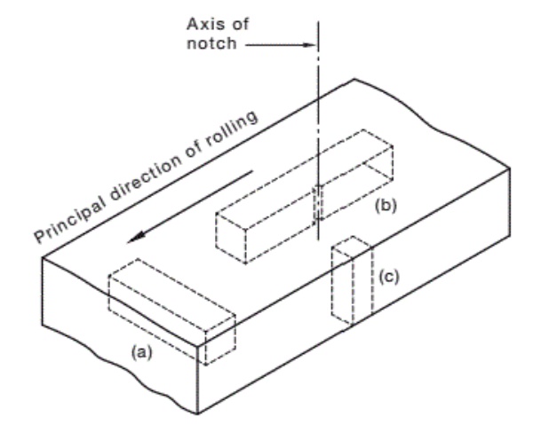
FIGURE 1 ORIENTATION OF TEST PIECE
9.3 Preparation of test pieces for mechanical testing
9.3.1 General
Test specimens may be straightened cold before preparation, in accordance with this Standard. A test piece that shows defective machining or develops flaws may be discarded and another test specimen may be submitted.
9.3.2 Tensile test piece
A test piece for tensile testing shall be prepared in accordance with AS 1391. For material less than or equal to 30 mm in thickness, a non‑proportional test piece of full‑product thickness in accordance with Table C2 of AS 1391‑2007 shall be used.
For material greater than 30 mm in thickness, either a proportional cylindrical test piece from as close as possible to the quarter thickness position or a non‑proportional test piece of full‑product thickness shall be used.
9.3.3 Impact test piece
The axis of the notch shall be perpendicular to the rolled surface of the plate. Test pieces shall be prepared in accordance with AS 1544.2 and with the following, as appropriate:
- (a) Plates of nominal thickness less than 8 mm For plates of nominal thickness less than 8 mm a 10 mm × full thickness test piece shall be used. In such a case, minimum absorbed energy values of 10 mm × 5 mm test pieces apply.
NOTE: For nominal thicknesses less than 6 mm impact tests should not be required. - (b) Plates of nominal thickness from 8 mm to 20 mm For plates of nominal thickness from 8 mm to 20 mm, material within 1 mm from the surface shall not be included.
Where possible, machine standard 10 mm × 10 mm test pieces shall be used. If the material is too thin to permit the preparation of 10 mm × 10 mm test pieces, tests shall be carried out on 10 mm × 7.5 mm or 10 mm × 5 mm subsidiary test pieces as specified in AS 1544.2. - (c) thicknessfrom20 mm32 mmMachinestandardt010 mm x 10 mm test pieces shall be used. Material within 3 mm from the plate of nominal Plates surface shall not be included.
- (d) Plates of nominal thickness greater than 32 mm Machine standard 10 mm x 10 mm test pieces with the major axis of the test piece as close as possible to the quarter thickness position of the plate shall be used.
9.3.4 Through‑thickness tensile test
A test piece of 10 mm diameter (S₀) for through‑thickness tensile testing shall be prepared as follows:
- (a) Plates of nominal thickness less than or equal to 40 mm A cylindrical test piece of full plate thickness shall be prepared by making welded extensions on the plate. Welding by suitable methods shall be carried out giving a strong bond without causing any marked alteration in the mechanical properties (see Note 1).
- (b) Plates of nominal thickness greater than 40 mm A cylindrical test piece of full plate thickness shall be prepared without welded extensions provided that a minimum of 6 mm on either side is used for heads or other means of fastening the test piece in the tensile testing machine.
NOTES:
1 Friction welding, manual metal‑arc welding using properly handled low hydrogen consumables, and stud welding in accordance with AS/NZS 1554.2 are preferred methods for attaching the extensions.
2 This Standard does not cover through‑thickness tested grades with nominal thickness less than 12 mm.
3 When nominal plate thickness t ≤ 25 mm and specimen geometry does not allow a valid test to be performed, a 6 mm diameter (S₀) test piece may be used in lieu of a 10 mm diameter test piece.
9.4 Mechanical testing
9.4.1 Tensile test
A tensile test shall be made on each test piece prepared from each test sample specified in Clause 9.1.
The tensile test shall be carried out in accordance with AS 1391. The rate of straining when approaching the yield stress shall be within the limits of the conventional straining rate as specified in AS 1391.
Elongation results shall be reported on a gauge length L₀ equal to 5.65√S₀ where S₀ is the cross‑sectional area of the test piece before testing. Conversion of results from a non‑proportional gauge length shall be in accordance with ISO 2566‑1.
For test pieces with a cross‑sectional area greater than 1000 mm², the minimum elongation after conversion to the gauge length of 5.65√S₀, shall be reduced by 2% from that given in Table 8.
9.4.2 Charpy V‑notch impact test
One test in accordance with AS 1544.2 shall be carried out on each of three test pieces prepared from each test sample specified in Clauses 9.1 and 9.2.
9.4.3 Through‑thickness tensile test
If through‑thickness testing is required for the grade, take two test samples from a sample off either end of any one rolled parent plate in the batch.
The rate of straining when approaching the yield stress shall be within the limits of the conventional straining rate as specified in AS 1391.
10 MECHANICAL PROPERTIES
10.1 Tensile tests
For tensile tests carried out in accordance with Clause 9.4.1, the yield stress, tensile strength and elongation, shall conform to the limits given in Table 8 for the appropriate grade.
For the specified yield stress in Table 8, the upper yield stress (ReH) shall be determined, or wherever this is not pronounced, either the 0.2% proof stress (Rp0.2) or the 0.5% total elongation proof stress (R0.5), may be used.
Where a pronounced lower yield stress (ReL) is present, the value determined for ReL may be used in place of ReH where it complies to the ReH requirements in Table 8.
| Grade suffix | % |
|---|---|
| Z15 | 15 |
| Z25 | 25 |
| Z35 | 35 |
| Grade designation (see Note 4) |
Minimum yield stress, ReH MPa |
Minimum tensile strength, Rm MPa |
Minimum elongation on a gauge length of 5.65√S₀ (see Notes 1 and 5) % |
|||||||||||
|---|---|---|---|---|---|---|---|---|---|---|---|---|---|---|
| Thickness mm |
Thickness mm |
Thickness mm |
||||||||||||
| ≤8 | >8 ≤12 |
>12 ≤20 |
>20 ≤32 |
>32 ≤50 |
>50 ≤80 |
>80 ≤150 |
>150 ≤200 |
≤20 | >20 ≤150 |
>150 ≤200 |
≤20 | >20 ≤150 |
>150 ≤200 |
|
| 200 | 200 | 200 | — | — | — | — | — | 300 | 300 | 290 | 24 | 24 | 23 | |
| 250 (see Note 2) | 280 | 260 | 250 | 250 | 250 | 240 | 230 | 220 | 410 | 410 | 400 | 22 | 22 | 21 |
| 300 | 320 | 310 | 300 | 280 | 280 | 270 | 260 | 250 | 430 | 430 | 420 | 21 | 21 | 20 |
| 350 | 360 | 360 | 350 | 340 | 340 | 340 | 330 | 320 | 450 | 450 | 450 | 20 | 20 | 19 |
| 400 | 400 | 400 | 380 | 360 | 360 | 360 | — | — | 480 | 480 | — | 18 | 18 | 17 |
| 450 | 450 | 450 | 450 | 420 | 400 | — | — | — | 520 | 500 | — | 16 | 18 | — |
| WR350 | 340 | 340 | 340 | 340 | 340 | 340 | — | — | 450 | 450 | — | 20 | 20 | — |
— = no specified limit
NOTES:
1 Elongation need not be determined for floorplate.
2 For grade designation 250, the minimum tensile strength requirement does not apply to material under 6 mm thick.
3 Recommendations for cold-bending and hot-forming of plates are given in Appendix C.
4 Tensile test requirements are the same for all impact tested, through thickness tensile tested and fine grained variants.
5 For test piece cross-sectional area > 1000 mm², minimum elongation is reduced by 2%, see Clause 9.4.1.
10.2 Impact test
For impact tests, carried out in accordance with Clause 9.4.2, the absorbed energy values shall conform to the limits given in Table 9.
| Grade designation | Impact designation (see Notes 1 and 2) |
Test temperature °C |
Minimum absorbed energy, J | |||||
|---|---|---|---|---|---|---|---|---|
| Size of test piece | ||||||||
| 10 mm × 10 mm | 10 mm × 7.5 mm | 10 mm × 5 mm | ||||||
| Average of 3 tests |
Individual test |
Average of 3 tests |
Individual test |
Average of 3 tests |
Individual test |
|||
| 250 300 350 400 |
L0 | 0 | 27 | 20 | 22 | 16 | 18 | 13 |
| L15 | -15 | |||||||
| L20 | -20 | |||||||
| L40 | -40 | |||||||
| 400 450 |
Y20 | -20 | 40 | 30 | 32 | 24 | 28 | 21 |
| Y40 | -40 | |||||||
| 450 | S0 | 0 | 70 | 50 | ||||
| WR350 | L0 | 0 | 27 | 20 | 22 | 16 | 18 | 13 |
| L20 | -20 | |||||||
NOTES:
1 Grades with impact designations with lower test temperatures are directly replaceable for grades with designations with higher test temperatures and/or lower minimum energies. For example, Grades with Y40 designation can be used in place of grades with Y20, L40, L20, L15 and L0 designations. Grades with L40 designations can be used in place of grades with L20, L15 and L0 designations.
2 Impact testing for S0 only applies for plates with a nominal thickness greater than 12 mm.
10.3 Through‑thickness tensile test
The percentage reduction of the cross‑sectional area after fracture (Z) shall be determined by the following equation:
Z = ((S₀ - S) / S₀) × 100
where
S₀ = original cross‑sectional area of the test piece, in square millimetres = πd²/4
S = cross‑sectional area after fracture, in square millimetres = (π/4)·((a+b)/2)²
where a and b are the measurements of two perpendicular diameters, in millimetres; where the fracture is elliptical in shape, a and b correspond to the axes of the ellipse.
The percentage reduction of the cross‑sectional area after fracture (Z) shall conform to the limits given in Table 7.
10.4 Heat treatment
If it is intended to reheat the grades defined in this Standard above 620°C, the purchaser should discuss the application and the reheating treatment with the manufacturer. Refer Paragraphs A5 and C2.
NOTE: The mechanical properties of these grades can be affected by any reheating that may be applied for its end use.
11 IDENTIFICATION, TEST AND INSPECTION CERTIFICATES
11.1 Identification
All product supplied to this Standard shall be identified by a mark with the following requirements:
- (a) Reference to this Standard, i.e. AS/NZS 3678.
- (b) The manufacturer's name or mark, or both.
- (c) The grade of steel (see Clause 4).
- (d) The identification of the heat of steel from which it was made.
- (e) Plate or identification numbers allowing the product to be traced to a test certificate.
- (f) The nominal product dimensions.
- (g) The marking specified in Items (a) to (f) shall be: (i) Produced at the time of manufacture. (ii) Legible and durable to the point of fabrication. (iii) Applied to each individual piece supplied. (iv) Not be detrimental to the use of the product.
If the identified portion of the product is subsequently removed, then these identifications shall be transferred to each remaining portion of the product.
Where identification is by means of die‑stamping, low‑stress stamps shall be used for impact tested grades.
NOTES: 1 Products not marked with the provisions specified in this Clause are non‑compliant with this Standard. 2 Manufacturers making a statement of compliance with this Standard on a product, packaging, test certification, inspection documentation or promotional material related to that product are advised to ensure that such compliance is capable of being verified.
11.2 Test and inspection certificates
11.2.1 General
A test and inspection certificate shall be available to the purchaser for all products manufactured to this Standard for each batch produced.
11.2.2 Transmission of test and inspection certificates by an intermediary
An intermediary shall only pass on either an original or a copy of the inspection documents provided by the manufacturer without any alteration, except as noted below. This documentation shall be accompanied by suitable means of identification of the product, in order to ensure the traceability between the product and the documentation.
Copying of the original document is permitted, provided that (a) traceability of product is maintained; and (b) the original manufacturer's document is available on request.
When producing copies of the original manufacturer's document, it is permissible to replace the original delivered quantity with the subsequent partial quantity.
NOTE: In the context of this Standard, an intermediary is a supplier and not a manufacturer (see Clauses 3.15 and 3.25 respectively).
11.2.3 Qualifications on test and inspection certificates
A test and inspection certificate shall provide the following:
- (a) Tests performed by a laboratory accredited by signatories to the International Laboratory Accreditation Corporation (ILAC) through their Mutual Recognition Agreement (MRA) for the specific tests described in this Standard. The appropriate logo or further details of the ILAC (MRA) signatory shall be noted on the document. NOTE: In Australia, ILAC (MRA) accredited bodies include National Association of Testing Authorities (NATA) and in New Zealand they include International Accreditation New Zealand (IANZ).
- (b) Additional tests, as agreed between the purchaser and manufacturer. NOTE: See Appendix A.
11.2.4 Minimum requirements for test and inspection certificates
All test and inspection certificates shall be in English alphanumeric characters, issued by the manufacturer and include the following:
- (a) Manufacturer's name.
- (b) Test certificate number.
- (c) Date of certification.
- (d) Product, testing specification and grade, e.g. AS/NZS 3678‑350L0 (see Clause 4).
- (e) Product delivery condition (see Clause 5.2) and dimensions width (mm) × thickness (mm) × length (mm), e.g. 2000.0 × 100.00 × 6000.
- (f) Product steelmaking process, e.g. basic oxygen or electric arc, slab cast (see Clause 5.1).
- (g) Unique product identifiers for the tested units and other product to which the inspection document or test certificate applies [see Clause 11.1(e)].
- (h) Heat number (from steel feed melting and casting).
- (i) Chemical analysis type, e.g. ladle or cast analysis 'L' or product 'P' (see Clauses 6.2 and 6.3).
- (j) For each test a laboratory identification providing traceability to the laboratory accreditation of the test type.
- (k) Chemical composition of all elements listed in Table 1 or Table 2 for the relevant grade including elements mentioned in the notes, boron (B) and any other element intentionally added (see Clause 6.4).
- (l) Where relevant, mechanical testing information as noted below: (i) Tensile tests to Clause 9.4.1 Position and orientation (see Clause 9.2), batch or item test, and results, i.e. ReH (or Rp0.2 or R0.5 or ReL), in MPa, Rm, in MPa, gauge length and % elongation (see Clause 10.1). (ii) Impact tests to Clause 9.4.2 Position and orientation (see Clause 9.2), batch or item test, test piece dimensions, in mm, (see Clause 9.3.3), tested temperature in °C and results, i.e. individual and average energy, in J, (see Clause 10.2). (iii) Through‑thickness tensile tests to Clause 9.4.3 Position and orientation (see Clause 9.2), batch or item test and results, i.e. % reduction in area (see Clause 10.3). (iv) Any additional heat treatment of the test piece (see Clause 9.1).
- (m) The manufacturing facility's quality management system's certifier and certification number.
- (n) The body assessing the product conformity of this Standard. For self‑assessment this is the manufacturer, the default scheme is this Standard (Appendix B).
- (o) A declaration from the manufacturer that the products supplied comply with the requirements of this Standard (refer to Clause 12) and Items (a) to (n) above. This shall be validated by the manufacturer's authorized inspection representative, including their name and position.
If the document has been validated by the purchaser's authorized representative or by an inspector designated by a third party their name and position shall be on the document.
12 SAMPLING AND TESTING TO DEMONSTRATE PRODUCT CONFORMITY
The minimum, sampling and testing procedures shall conform to Appendix B. Additional testing may be agreed between the manufacturer and the purchaser.
13 ROUNDING OF NUMBERS
13.1 General
For the purpose of deciding whether a particular requirement of this Standard is complied with, the determined value, observed or calculated, shall be rounded off in accordance with AS 2706.
The number of significant places retained in the rounded‑off value shall be the same as that of the specified value in this Standard.
13.2 Tensile properties
The determined value of tensile strength shall be rounded off to the nearest 10 MPa, and the determined value of yield stress shall be rounded off to the nearest 5 MPa.
14 MANIPULATION
Appendix C provides guidance on cold‑bending during fabrication.
APPENDIX A PURCHASING GUIDELINES (Informative)
A1 GENERAL
Australian/New Zealand Standards are intended to include the technical provisions necessary for the supply of materials referred to in the particular Standard, but do not purport to comprise all the necessary provisions of a contract. The purchaser may specify the additional requirements or be given a choice of optional requirements. These are contractual matters to be agreed upon between the purchaser and the manufacturer, or the supplier.
This Appendix contains detailed explanations, advice and recommendations on the information to be supplied by the purchaser at the time of order.
The objective of this Appendix is to avoid misunderstandings and to result in the purchaser receiving satisfactory products and services.
A2 INFORMATION TO BE SUPPLIED BY THE PURCHASER
The purchaser should consider and supply the following information at the time of order, after making due reference to the explanation, advice and recommendations contained in this Appendix:
- (a) Product form required, i.e. plate, floorplate or slab (see Clauses 3.19, 3.9 and 3.24 respectively).
- (b) Quantity and delivery instructions (dates, schedules, delivery point).
- (c) Dimensions of section, e.g. thickness, width, length.
- (d) Designation of grade and Standard number (see Clause 4).
- (e) Type of edge required, i.e., trimmed or untrimmed edge (see Clause 3.6).
- (f) Whether documentation certifying the product conformity requirements (see Appendix B) is required.
- (g) Any limitations in respect of packaging, e.g. number or mass of plates per pack, packaging materials.
- (h) Whether it is the intention of the purchaser to inspect the steel at the manufacturer's works (see Paragraph A4).
- (i) Any information concerning processing or end‑use that the purchaser considers would assist the manufacturer.
- (j) Whether the steel is to be ultrasonically tested (see Paragraph A3).
- (k) Whether a product analysis is required and the frequency of the analysis (see Clause 6.3).
- (l) Whether special tolerances on dimensions are required.
- (m) Allowing additions of residual elements (see Clause 6.4).
- (n) Heat‑treated condition of steel, i.e. as‑rolled or normalized (see Clause 5.2).
- (o) Zinc coating requirements (refer to AS/NZS 2312.2). As a guide, recommendations for suitable chemistry of steels are provided in AS/NZS 2312.2. Further information is available from the Galvanizers Association of Australia (GAA) and Galvanizing Association of New Zealand (GANZ).
- (p) For as‑rolled steel, the condition of test pieces, i.e. as‑rolled or normalized (see Clause 9.1).
- (q) If fine grained steelmaking practice is required on steels supplied (see Clause 4.6).
- (r) If products are to be ordered descaled (see Clause 8.2).
- (s) If repair by welding is not allowed (see Clause 8.4).
- (t) If the product is for seismic and fracture critical applications to NZS 3404.1, (see Appendix F).
NOTE: Any special or supplementary requirements of this Standard are subject to agreement between the purchaser and the manufacturer, or the supplier at the time of enquiry and order, and should be stated on the order.
A3 ULTRASONIC TESTING
If ultrasonic testing is required by the purchaser, the method of test to be used and the limits of acceptance should be determined at the time of enquiry and order.
The test method and quality grade should be in accordance with AS 1710.
A4 INSPECTION
If it is the purchaser's intention to undertake any of the following functions at the manufacturer's works, this should be notified at the time of order, and should be accomplished in a manner, which will not interfere with the operation of the works. The functions are as follows:
- (a) Inspect the product during manufacture.
- (b) Select and identify the test samples.
- (c) Witness the tests being made.
The manufacturer should provide all reasonable facilities to enable the purchaser to be satisfied that the product complies with this Standard.
A5 HEAT TREATMENT
The mechanical properties of these grades can be affected by any reheating that may be applied for its end use.
If it is intended to reheat these grades above 620°C the purchaser should discuss the application and the proposed reheating treatment with the manufacturer.
APPENDIX B PRODUCT CONFORMITY (Normative)
B1 SCOPE
This Appendix sets out the means by which product conformity evaluation shall be demonstrated by the manufacturer or supplier by (a) initial type testing; and (b) factory production control, including a minimum testing and inspection frequency plan.
Testing and inspection of one or two samples does not provide an acceptable representation of actual variability in a batch of unidentified steel.
NOTE: The result of testing and inspecting such a sample could fall within or outside the standard range by chance and does not present a valid picture of the characteristics being evaluated.
The product conformity requirements shall enable conformity assessment to be made by a manufacturer or supplier (first party), a user or purchaser (second party), or an independent body (third party), and shall not be dependent on a quality management system Standard.
NOTE: An example of a quality management system Standard is AS/NZS ISO 9001.
B2 INITIAL TYPE TESTING
B2.1 General
An initial type testing program shall be carried out in accordance with Paragraph B2.2 under the sole responsibility of the manufacturer of the products before they are first placed onto the market.
Such a program shall be carried out for each grade designation with the highest strength and impact properties and largest reduction of area, which a manufacturer places on the market (Tables 7 and 8). Additional programs are required for lower grade designations with more stringent impact designations and higher reduction of area requirements. The testing program shall include the thickest product in each of the thickness ranges specified in Table 7 of this Standard.
Initial type testing shall be performed on first application of this Standard. Tests previously performed in accordance with the provisions of this Standard (same product, same characteristic(s) test method, sampling procedure, system of attestation of conformity, etc.) may be taken into account. In addition, the initial type testing shall be performed at the beginning of a new method of production, and/or using a new facility or equipment.
B2.2 Minimum sampling and testing plan
The initial type testing and inspection program comprises of routine testing and inspection at a higher frequency to establish the capabilities of the manufacturing process to produce the steel product. Table B1 provides the minimum testing and inspection frequency plan for type testing. The results of all type tests shall meet the requirements of this Standard.
| Characteristic | Clause | Requirement | Test method | Frequency |
|---|---|---|---|---|
| Designation | 4 | Steel grade designation correct | Visual inspection | Once |
| Manufacturing process | 5.1 | Determine steel making process | Records inspection | Each heat, minimum of 5 |
| 5.2 | Determine delivery condition | |||
| Chemical composition | 6.2 and 6.3 | Cast and product analysis | AS/NZS 1050 and analysis methods | Each heat, minimum of 5 heats |
| 6.4 | Residual elements analysis | |||
| Manufacturing tolerances | 7 | Gauge | AS/NZS 1365 | Each product rolled |
| Width and length | First plate after set-up then each 8 hours* | |||
| Flatness, edge camber and out of square | First plate after set-up then each 120 hours* | |||
| Freedom from defects | 8.2 | Surface defects | Visual inspection | Each plate |
| Mechanical properties | 10.1 | Tensile strength, yield stress and elongation | In accordance with Clauses 9 and 10 | As rolled: test 6 parent patterns from each heat for a minimum of first 5 heats after set-up. Normalized: test each discrete piece loaded in to the heat treatment unit. |
| 10.2 | Toughness for impact tested grades | |||
| 10.3 | Reduction of area for through-thickness tested grades | |||
| Identification and certification | 11.1 | Identification | Visual inspection | Each plate |
| 11.2 | Test and inspection certificates | Records inspection | Each document |
* Time is operating hours.
B3 PRODUCTION TESTING AND INSPECTIONS
B3.1 Minimum batch testing and inspection
The manufacturer shall ensure that all products conform to the minimum frequency requirements of production testing and inspections, as defined in Table B2.
| Characteristic | Clause | Requirement | Test method | Frequency |
|---|---|---|---|---|
| Manufacturing process | 5.1 | Determine steel making process | Records inspection | Each heat |
| 5.2 | Determine delivery condition | |||
| Chemical composition | 6.2 and 6.3 | Cast and product analysis | AS/NZS 1050 and analysis methods | Each heat |
| 6.4 | Residual elements analysis | |||
| Manufacturing tolerances | 7 | Gauge | AS/NZS 1365 | Each product rolled |
| Width and length | First plate after set-up then each 8 hours* | |||
| Flatness, edge camber and out of square | First plate after set-up then each 120 hours* | |||
| Freedom from defects | 8.2 | Surface defects | Visual inspection | Each hour |
| Mechanical properties | 9 and 10.1 | Tensile strength, yield stress and elongation | To Clauses 9 and 10 | To Paragraph B3.2 |
| 9 and 10.2 | Toughness for impact tested grades | |||
| 9 and 10.3 | Reduction of area for through-thickness tested grades | |||
| Identification and certification | 11.1 | Identification | Visual inspection | Each plate |
| 11.2 | Test and inspection certificates | Records inspection | Each document |
* Time is operating hours.
B3.2 Test batch
A test batch is a group of rolled parent plates consisting of finished steel of the same yield stress gradation (see Table 7) and product form, treated in the same manner and from the same heat.
NOTE: In ISO 404, a test batch is called a 'test unit'.
A sample product representative of the batch shall be selected and samples taken as follows:
- (a) One sample for a batch not exceeding 70 tonnes.
- (b) One additional sample for the balance of the batch. If either batch includes steel of more than one thickness, a further sample shall be taken for each variation in thickness, above or below the thickness of the first test piece selected within each thickness range as set out in Table B3.
- (c) If specified at the time of order, take a sample for each rolled parent plate.
- (d) Where the product is heat treated by normalizing, one sample shall be taken from each discrete piece loaded in to the heat treatment unit.
| Nominal thickness of the product (t) mm |
Nominal thickness variation mm |
|---|---|
| 3 ≤ t ≤ 25 | ±5 |
| 25 < t ≤ 250 | ±25 |
B3.3 Conformity
Each test batch conforms to this Standard if all of the samples tested give results that are within the specified limits. If any of the properties of the tested samples give results outside the specified limits, the requirements of Paragraph B5.2 shall apply.
B3.4 Invalidation of test results
Test results that are affected by improper sampling and/or preparation of test pieces and/or tests being carried out improperly shall be considered invalid. The test shall be repeated with a new test piece.
B4 FACTORY PRODUCTION CONTROL
B4.1 General
The manufacturer shall establish, document and maintain a factory production control (FPC) system to ensure that the products placed on the market conform with the stated performance characteristics. The FPC system shall consist of procedures, regular inspections and tests and/or assessments and the use of the results to control raw and other incoming material or components, equipment, the production process and the product.
A quality management system covering the requirements of this document shall be considered to satisfy the requirements of an FPC.
NOTE: An example of an appropriate quality management system Standard is AS/NZS ISO 9001.
B4.2 Equipment
B4.2.1 Testing
All weighing, measuring and testing equipment shall be calibrated and regularly inspected according to documented procedures, frequencies and criteria.
B4.2.2 Manufacturing
All equipment used in the manufacturing process shall be regularly inspected and maintained to ensure use, wear or failure does not cause inconsistency in the manufacturing process. Inspections and maintenance shall be carried out and recorded in accordance with the manufacturer's written procedures.
B4.3 Raw materials
The specification of all incoming raw materials shall be documented, as shall the inspection scheme for ensuring their conformity. All manufacturing process and steel feed shall comply with the requirements of Clause 5.
B4.4 Product testing and evaluation
The manufacturer shall establish procedures to ensure that the stated values of all the characteristics are maintained. The characteristics and the means of control shall be in accordance with the minimum requirements listed in Table B2.
B5 NONCONFORMING PRODUCTS
B5.1 General
The manufacturer shall have written procedures specifying the processing of nonconforming product.
B5.2 Retests
The requirements of ISO 404:2013, Clause 8.3.4 apply.
B5.3 Repair
All repaired product shall be inspected and meet the requirements of this Standard.
B6 DOCUMENTATION
The results of all testing programs shall be recorded and such records shall be maintained and be made available for inspection for a period of at least 5 years after the date when that last product to which the test program refers to was delivered. Results for initial type testing shall be kept for the life of the product in the market.
Documentation shall include information to be made available to the purchaser, plus manufacturing process, physical and mechanical properties, inspection and testing, and test procedures.
APPENDIX C COLD‑BENDING AND HOT‑FORMING OF PLATE DURING FABRICATION (Informative)
C1 COLD‑BENDING
For steel plates manufactured in accordance with this Standard, the minimum inside radii for cold‑bending during fabrication should be in accordance with Table C1. The recommendations given in Table C1 assume that the plate edge has been conditioned prior to bending.
Guidelines for steel grade selection, where fracture toughness is important, are given in the sections on brittle fracture in AS 4100 and NZS 3404.1.
| Plate thickness (t) mm |
Bend direction (see Notes 1 and 2) |
Inside radius, mm | |||
|---|---|---|---|---|---|
| Grade designation | |||||
| 200 | 250 and 300 | 350 and 400 | 450 and WR350 | ||
| ≤6 | Transverse | 0.5t | 1.0t | 1.5t | 1.5t |
| Longitudinal | 1.0t | 1.5t | 2.25t | 2.25t | |
| >6 ≤10 | Transverse | 1.0t | 1.5t | 2.0t | 2.0t |
| Longitudinal | 1.5t | 2.25t | 3.0t | 3.0t | |
| >10 ≤20 | Transverse | 1.5t | 2.0t | 2.5t | 3.0t |
| Longitudinal | 2.25t | 3.0t | 3.75t | 4.5t | |
| >20 ≤50 | Transverse | — | 4.0t | (see Note 3) | Hot-form |
| Longitudinal | — | 6.0t | (see Note 4) | Hot-form | |
| >50 ≤150 | Transverse | — | (see Note 4) | Hot-form | — |
| Longitudinal | — | (see Note 4) | Hot-form | — | |
NOTES:
1 A transverse bend is one where the axis of the bend is at right angles to the direction of rolling.
2 A longitudinal bend is one where the axis of the bend is parallel to the direction of rolling.
3 Where radii in the approximate range of 3t to 10t is desired, bending should be carried out by hot-forming. Where large bend radii (greater than 10t) is desired, bending may be carried out by cold-forming. With plate thickness greater than 40 mm, slight warming to approximately 75°C is recommended before forming.
4 It is generally desirable to hot-form. If bend radii is large (greater than 15t) and the steel is preheated to approximately 75°C, cold-forming methods should be satisfactory.
5 The recommended minimum bending radii of floorplates are as above except that where the raised figures are in tension, more liberal radii should be used.
C2 HOT‑FORMING
Where hot‑forming is required, it should be carried out within the temperature ranges of 580°C to 620°C or 870°C to 930°C (see Paragraph A5).
APPENDIX D NOT USED
This Appendix is intentionally left blank to maintain consistency of appendix sequence with AS/NZS 1163 and the AS/NZS 3679 series.
APPENDIX E NOT USED
This Appendix is intentionally left blank to maintain consistency of appendix sequence with AS/NZS 1163 and the AS/NZS 3679 series.
APPENDIX F STEEL FOR SEISMIC AND FRACTURE CRITICAL APPLICATIONS (NEW ZEALAND ONLY) (Normative)
F1 ADDITIONAL REQUIREMENTS FOR SEISMIC AND FRACTURE CRITICAL APPLICATIONS
Additional requirements for steel used for seismic and fracture critical applications are set out in NZS 3404.1. Where steel is required to be supplied for these applications, the steel shall comply with those additional requirements and as set out in this Appendix.
F2 DESIGNATION
Grades for seismic and fracture critical applications shall be designated in accordance with the procedures specified in Clause 4.2 and have a S0 suffix as specified in Clause 4.3. The fine grained requirement is as specified in Clause 4.6.
Example: AS/NZS 3678‑300S0FG
F3 STEEL FOR SEISMIC APPLICATIONS
S0 grade shall be tensile tested according to Clauses 9.1, 9.2, 9.3.2. If determined in accordance with Clause 9.4.1, the yield stress and tensile strength of a test piece shall conform to the limits given in Table 7. The elongation, yield ratio and yield stress of a test piece shall also conform to the additional limits in Items 1, 2 and 3 given in Table F1.
The lower yield stress ReL shall be used for determining the limiting ratios in Table F1 for S0 grade seismic steels. The ReL value used shall be either (a) the ReL value determined in accordance with AS 1391 and reported on the mill test and inspection certificate; or (b) the ReL value calculated from the ReH value reported on the mill test and inspection certificate using a probability of 0.05 for a confidence level of 0.75. These values shall be published by the manufacturer and made freely available to the purchaser on request.
| Item | Requirement | Limit |
|---|---|---|
| 1 | Minimum percentage elongation after fracture (A) on a gauge length of 5.65√S₀ (see Note 2) | 25% |
| 2 | Maximum yield to tensile ratio (ReL/Rm) (see Note 2) | 0.8 |
| 3 | Maximum yield stress ReL (see Note 2) | <1.33fy (see Note 1) |
| 4 | Minimum absorbed energy for a test piece of size 10 mm × 10 mm tested at 0°C (see Notes 3, 4) | 70 J average 50 J individual |
NOTES:
1 fy is the grade nominal yield stress for the steel 16 mm thick.
2 The ReL, Rm and A values are the actual values recorded on the plate or batch test and inspection certificate.
3 Impact testing is only required for plates with a nominal thickness >12 mm.
4 The absorbed energy values are the actual absorbed energy values recorded on the plate or batch test and inspection certificate.
F4 STEEL FOR FRACTURE CRITICAL MEMBERS
The following requirements apply:
- (a) Steel shall be ordered with the fine grained steelmaking practice option (see Clause 4.6).
- (b) No weld repairs shall be performed to the steel (see Clause 8.4).
- (c) The removal of defects from a plate by grinding, or by chipping followed by grinding, shall not extend below the rolled surface by more than 0.5 mm for all thicknesses of material (see Clause 8.3).
- (d) Conformity as outlined in Appendix B shall apply.
NOTE: Fracture critical members are typically fatigue sensitive members in bridges and other structures as defined in NZS 3404.1.
BIBLIOGRAPHY
- AS 1710 Non‑destructive testing—Ultrasonic testing of carbon and low alloy steel plate and universal sections—Test methods and quality classification
- AS/NZS 2312.2 Guide to the protection of structural steel against atmospheric corrosion by the use of protective coatings — Part 2: Hot dip galvanizing
- AS/NZS 3679.1 Structural steel — Part 1: Hot‑rolled bars and sections
- AS/NZS 3679.2 Structural steel — Part 2: Welded I sections
- AS/NZS ISO 9001 Quality management systems—Requirements
© Standards Australia Limited
© The Crown in right of New Zealand, administered by the New Zealand Standards Executive
Jointly published by SAI Global Limited under licence from Standards Australia Limited, GPO Box 476, Sydney, NSW 2001 and by Standards New Zealand, PO Box 1473, Wellington 6140.
Visit our web sites www.standards.org.au www.standards.govt.nz
微信客服
专业客服在线解答

APP下载
随时随地查询现货